For optimal control over a single light source from two different spots, connect a pair of control points using a three-wire setup. This method allows you to operate the same fixture from multiple locations, increasing convenience and accessibility. Proper wiring is crucial to ensure safe operation and reliable performance, so understanding the specific wiring sequence is necessary.
Ensure that you use the right components: A typical setup involves two specialized electrical units, each designed to manage current flow in a distinct manner. These must be installed in locations where each control point is easily accessible, typically at opposite ends of a room or hallway. Each unit requires a connection to the fixture’s power line and a shared traveler wire that links the two.
Installation guidelines: The wiring configuration involves connecting the common terminal to the power source and the fixture, while the traveler terminals connect each of the units. Careful attention is needed to ensure that the traveler wires are correctly placed, preventing accidental short circuits and ensuring smooth operation when toggling between positions. For maximum efficiency, use appropriately rated wires and verify each connection with a voltage tester before securing the units in place.
Once completed, this setup provides the ability to control the same fixture from two distinct points. Proper installation ensures long-term safety and reduces the chances of malfunction or failure. Consider consulting with a professional electrician if you are unfamiliar with electrical work to ensure compliance with local building codes and safety standards.
Wiring Layout for a Dual-Control Circuit

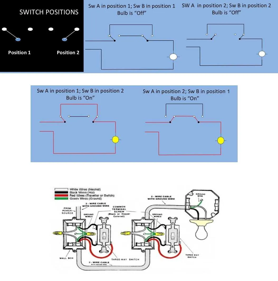
To wire a system with two controllers that operate the same fixture, ensure both are connected to the same electrical circuit. One controller should connect to the power source, while the second should link to the fixture’s terminal. Both controllers will have two terminals for conducting electricity: one for the input current and another for the output current. This allows alternating control from two locations.
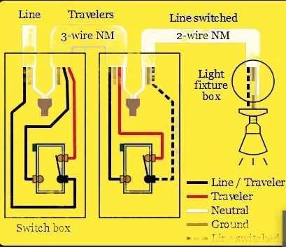
The common terminal on the first controller must be linked to the incoming live wire from the power supply. The second controller’s common terminal should be connected to the fixture’s live terminal. Each controller will have two traveler terminals. Use these to connect the corresponding terminals on both controllers with two wires running between them. This setup enables you to control the same fixture from two different positions, ensuring flexibility in controlling the circuit.
For safety, use appropriately rated wire and connectors for the voltage and current in your specific installation. Make sure to double-check connections, as faulty wiring can cause malfunctions or safety hazards. Test the system to ensure both controllers work as intended, providing seamless operation when either is engaged.
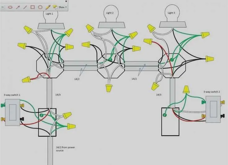
Wiring Diagram for a 3-Way Switch Setup

To wire a setup with two control points, follow these steps to ensure proper connections and functionality.
- Power Source: Connect the hot wire from the power supply to the common terminal of the first device.
- Traveler Wires: Run two traveler wires between the traveler terminals on both devices. These wires allow the control points to send signals to one another.
- Grounding: Properly ground each device by connecting the ground wire to the metal box or the ground terminal on each device.
- Second Control Point: At the second location, connect one traveler wire to each of the two traveler terminals and the common terminal to the load (or fixture).
- Load Connection: Ensure the load wire is connected to the common terminal at the second control point, completing the circuit when the control points are toggled.
- Verify the connections before testing.
- Ensure the traveler wires are connected correctly at both devices to prevent malfunction.
Once all connections are made, the circuit will allow for controlling the fixture from both locations. Make sure to use appropriate wire gauges and secure all terminals tightly to avoid any electrical hazards.
How to Identify Common, Traveler, and Ground Terminals
To identify the common, traveler, and ground terminals in a dual-control circuit, start by locating the terminal with a dark or black screw; this is typically the common terminal. This is the one that receives power from the power source and is crucial for the operation of the system.
The two terminals with brass-colored screws are the traveler terminals. These are used to carry current between the two control points. You’ll notice that the brass screws are often positioned opposite each other on the component.
The ground terminal, usually a green screw or a bare metal tab, is where you connect the grounding wire. It’s an essential safety feature to protect against electrical faults.
Remember: the common terminal always receives the live feed, while the travelers connect to the second control’s corresponding terminals. The ground wire ensures that any faulty current is safely discharged.
Step-by-Step Instructions for Connecting a 3-Way Switch System

Start by turning off the power at the breaker to prevent any accidents. Use a voltage tester to ensure no electricity is flowing through the wires before beginning work.
Identify the common terminal on the first device. This terminal will be connected to the hot wire from the power source. Use a wire stripper to remove about 1 inch of insulation from the wire before attaching it securely to the common terminal.
On the second device, locate the common terminal as well. This is where you will connect the wire leading to the light fixture or other controlled load. Again, strip 1 inch of insulation before making the connection.
For the traveler terminals, connect the two devices with two separate wires. These wires will link the traveler terminals from the first device to the traveler terminals on the second one. Ensure the connections are tight and the wires are firmly secured under the screws.
Next, connect the ground wire to the green terminal on both devices. This step is crucial for safety, ensuring the system is grounded properly.
If necessary, secure the devices into the electrical box, making sure that no wires are pinched. Finally, install the faceplates to cover the devices.
Once the devices are installed and secured, restore power at the breaker. Test the operation by toggling both devices to ensure that the system is working as expected.