Connect the white conductor to the grounding point on the tow vehicle’s frame. This line ensures that all lighting and auxiliary features share a reliable return path, preventing voltage drops or signal interference. Always secure the contact using a self-tapping screw or factory ground stud.
For brake activation, the blue cable must be routed through an electric controller and terminated at the electromagnet terminal on the towing side. Use a minimum 12-gauge wire to maintain consistent amperage, especially on longer hauls or heavy-duty setups.
Attach the green strand to the right-turn and stop circuit. This connection syncs with the vehicle’s right signal lamp. Confirm operation by checking flash rate consistency and ensuring no voltage leaks when brakes are applied.
The yellow lead handles the left-turn and stop mechanism. Connect this path to the corresponding output on the signal module. Ensure continuity with a multimeter, and always double-check polarity before final assembly.
For taillight functionality, utilize the brown channel. This route must carry steady 12V during night operations and illuminate all side markers. Protect this path using inline fuses rated between 10–15A.
Auxiliary charging requires the black wire, typically linked to the battery’s positive terminal. Insert a 30A circuit breaker to shield from short circuits or overload scenarios during power transfer.
Finally, the purple line may serve reverse signal duties or backup lighting. Route it from the reverse lamp feed and confirm signal presence only when the gear is in reverse. This circuit helps align trailers or activate rearview systems in low-light environments.
7-Way Connector Configuration for Towing Systems

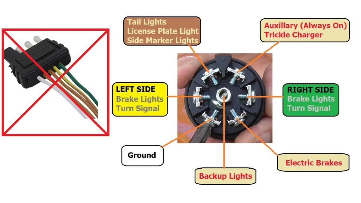
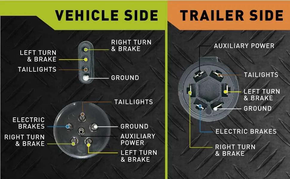
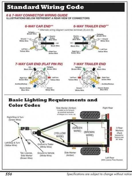
Use the standard RV blade pattern with a 2 o’clock ground contact and a 5 o’clock power input. Assign the 1 o’clock terminal to electric brake control and the 7 o’clock for left signal and stop lamp. The 4 o’clock position handles the reverse light, while the 8 o’clock delivers the right turn and brake feed. Tail and running lights connect to the 10 o’clock slot. Ensure the center terminal is reserved for auxiliary functions, typically a 12V supply to charge onboard batteries.
Always verify polarity with a multimeter before finalizing connections. Miswiring brake and auxiliary feeds may cause system faults. Secure each terminal using dielectric grease to prevent corrosion. Follow color-code conventions: white for ground, black for power, blue for brakes, green and yellow for right and left signals respectively, brown for tail lamps, and purple for reverse.
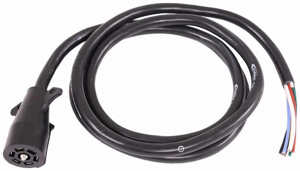
Understanding Each Wire Function in the Hopkins 7-Way Connector

Match each terminal to its specific task using the following layout to ensure reliable signal flow and safety:
- Ground (White): Ensures return path for all circuits. Must be securely fastened to a clean chassis surface.
- Tail Lamps (Brown): Powers rear position lights, license plate illumination, and marker lamps. Connect to vehicle’s lighting control.
- Left Turn/Brake (Yellow): Transmits both turn signal and brake signal for the left side. Splice into left-side rear light harness.
- Right Turn/Brake (Green): Handles dual-function signal on the right. Use a dedicated output from the vehicle’s controller.
- Electric Brakes (Blue): Sends variable voltage from the brake controller. Route through a fuse-protected path.
- Reverse Lights (Purple): Activates rear-facing lamps when in reverse. Wire into backup circuit of the towing vehicle.
- 12V Auxiliary (Black or Red): Supplies constant power for interior lighting, battery charging, or accessories. Use an inline circuit breaker (30A recommended).
Verify continuity and proper voltage before finalizing connections. Protect all terminations with heat shrink or waterproof connectors to avoid corrosion or shorts.
Step-by-Step Guide to Rewiring a Hopkins 7 Pin Trailer Plug

Start by disconnecting the tow vehicle’s battery to prevent shorts. Use a circuit tester to confirm power is off before proceeding.
Unscrew the rear cover of the connector housing and pull out the internal terminals. If corroded, replace them rather than attempting to clean them.
Strip each wire back approximately 3/8 inch. Match each conductor with its corresponding terminal: brown for tail illumination, green for right blinkers and brakes, yellow for the left side, red for auxiliary power, blue for electric brakes, white for grounding, and black for the charge line.
Secure each wire under its designated screw using a small flathead driver. Tighten just enough to prevent movement without cutting the copper.
Route the bundle through the strain relief and ensure the jacket is clamped securely to avoid stress on individual lines. Reattach the rear shell, making sure no wires are pinched.
Reconnect the vehicle battery and test each function–use a multimeter or a test light to verify continuity and voltage under load conditions.
Apply dielectric grease to internal contacts to prevent oxidation and ensure long-term reliability.
Troubleshooting Common Wiring Issues with Hopkins 7-Way Plugs
Begin by checking continuity between each connector terminal and its corresponding endpoint using a multimeter set to resistance mode. A reading above 1 ohm typically indicates corrosion or a loose crimp.
If the turn signals or brake lights fail, test the brown and red leads for voltage with the ignition and lights on. A reading below 12V suggests a damaged feed or compromised ground.
Inspect the black lead, typically used for auxiliary power, for voltage drop under load. Values under 11.5V while powering a device signal high resistance–often caused by oxidized contacts or frayed strands within the jacket.
Should running lights flicker or go dark, verify that the white return path is solidly attached to bare metal on the frame. A high-impedance return can result in intermittent performance or complete failure under moisture exposure.
For electric brake systems, confirm the blue conductor provides at least 12V when the brake controller is fully engaged. Lower values may indicate undersized wire gauge, internal breaks, or a controller malfunction.
Use dielectric grease when reconnecting terminals to prevent future oxidation, and ensure all contacts are firmly seated within the molded shell to avoid vibration-induced failures.