When installing or troubleshooting the cooling system in your equipment, ensure that you follow the correct electrical setup to avoid malfunctioning or damage to the components. Properly connecting the control unit to the operational switches is crucial for smooth and efficient performance.
First, check the power supply voltage and make sure it aligns with the specifications provided by the manufacturer. Incorrect voltage can cause overheating, short circuits, or complete failure of the components. For most models, it is essential that the circuit is properly grounded to prevent electrical surges.
Next, map the control contacts to the necessary terminals on the motor unit. This step is vital for achieving the desired start-stop sequence and ensuring that the motor receives the correct signals from the control panel. Use a multimeter to confirm that the continuity between terminals is accurate before powering the system.
Be mindful of the control switch ratings, as they must be compatible with the load requirements. Always use connectors that are rated for the amperage to avoid overheating or potential damage to the system.
Electrical Control Setup for Cooling System
For efficient operation of the cooling system, connect the motor to the control circuit with a proper switching mechanism. Ensure the input from the power source is securely connected to the system’s main contact points. The switch mechanism should be rated to handle the motor’s operating voltage and current without failure.
At the output terminals, securely wire the motor’s terminals to the corresponding relay contacts. Make sure that the connections are insulated properly to prevent short circuits. Check that the control side of the switch connects to the system’s temperature sensing mechanism, ensuring the motor activates only when the temperature exceeds the preset threshold.
Use a fuse with appropriate rating for circuit protection to prevent overload. This fuse should be placed near the power source to safeguard the entire system. If your system includes multiple components, connect the power supply to a central control unit to manage all connections efficiently and minimize wiring complexity.
Important: Double-check all connections to ensure there are no loose contacts. Tighten all screws and secure wiring to avoid potential system failures due to vibration or movement. Always test the system under operational conditions before full deployment.
Tip: Keep the manual for your system handy during installation for reference on specific connection requirements and ratings for the components used.
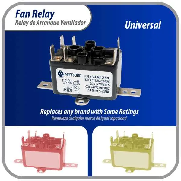
Understanding the Components in a Pr380 Fan Relay Circuit
The main components involved in a system like this include the control switch, the electrical contact points, the coil, and the associated wiring. The control switch triggers the activation of the system by sending a voltage signal to the coil. Once energized, the coil generates a magnetic field, which causes the contacts to either close or open, depending on the design of the switch. This action allows current to flow through the connected components, powering up the circuit.
The electrical contacts, typically made of durable materials such as silver or copper, are critical for ensuring a stable connection. Proper insulation and corrosion-resistant materials are vital for ensuring the longevity and reliability of the circuit, especially in high-stress environments. Over time, these contacts can wear out, causing failures or inefficiencies in the operation of the entire setup.
The coil plays a pivotal role by converting electrical energy into mechanical motion. The selection of a coil with the right specifications is crucial, as it affects both the speed and the efficiency of the switching process. Using coils with higher resistance or power ratings can impact the overall performance, so always match these ratings with the requirements of the system.
The accompanying wiring must be robust enough to handle the current load without excessive heat buildup. Insulation should be rated for the voltage levels in use, and the connections must be secure to avoid any short circuits or loose contacts. For optimal performance, consider using wires with a lower resistance to minimize energy loss and improve efficiency.
In summary, selecting the right components–such as a durable control switch, high-quality electrical contacts, properly rated coils, and well-insulated wiring–ensures the smooth functioning of the system and extends its operational lifespan. Regular maintenance checks and proper installation are key to preventing future malfunctions.
Step-by-Step Guide to Connecting the Pr380 Component Control System
Follow these precise steps for setting up the component control system. The process requires careful handling of connections to ensure proper operation.
- Prepare your tools and components:
- Insulated wire cutters and strippers
- Electrical tape
- Screwdriver
- Voltage tester
- Identify the terminals:
- Locate the terminals for power input, output, and ground on the control unit.
- Make sure to verify the correct pinout for each connection to avoid errors.
- Power connection:
- Connect the positive terminal of your power source to the input pin on the control module.
- Ensure a secure connection to prevent electrical interruptions.
- Grounding:
- Connect the grounding terminal from the module to a suitable metal surface or grounding bar.
- Double-check for solid, corrosion-free contact.
- Signal line setup:
- Run the signal wires from the output terminal of the control module to the corresponding component.
- Ensure the connections are insulated and properly secured to avoid shorts.
- Final checks:
- Use a voltage tester to verify that the connections are providing the correct output voltage.
- Test the system for functionality by powering on the control unit.
- If the unit operates as expected, confirm all wires are properly insulated and secured.
By following these steps, you will have successfully completed the setup, ensuring reliable operation of the component control system.
Troubleshooting Common Electrical Connection Problems in Pr380 Systems

When facing issues with a faulty electrical connection, start by inspecting all terminals for secure connections. Loose or corroded contacts can lead to unreliable operation. Ensure that all screws and bolts are tightly fastened and that no exposed wires are shorting against nearby metal parts.
Next, verify the power source by testing the input voltage. If the voltage is lower than required, there could be an issue with the circuit’s power supply or fuse. Use a multimeter to check the voltage at various points, ensuring it matches the specifications for the system.
If the system fails to trigger properly, check for any interruptions in the control circuit. Look for damaged or frayed wires that might prevent the correct signal transmission. Pay special attention to areas where wires bend or pass through tight spaces, as these are common points for wear and tear.
Another common issue arises when components fail due to overheating. Inspect the connectors and surrounding areas for signs of heat damage. If the components show discoloration or the insulation is melted, it’s time to replace them before continuing further troubleshooting.
If intermittent issues occur, inspect for ground faults. Use a continuity tester to check the ground connection. A weak or absent ground can cause unstable performance, leading to false triggers or system failure under load.
For systems that don’t start at all, ensure the switching mechanism is working correctly. Check for mechanical faults in the switching components, as these can prevent the system from engaging even when electrical connections are intact.