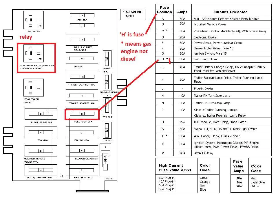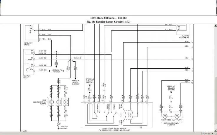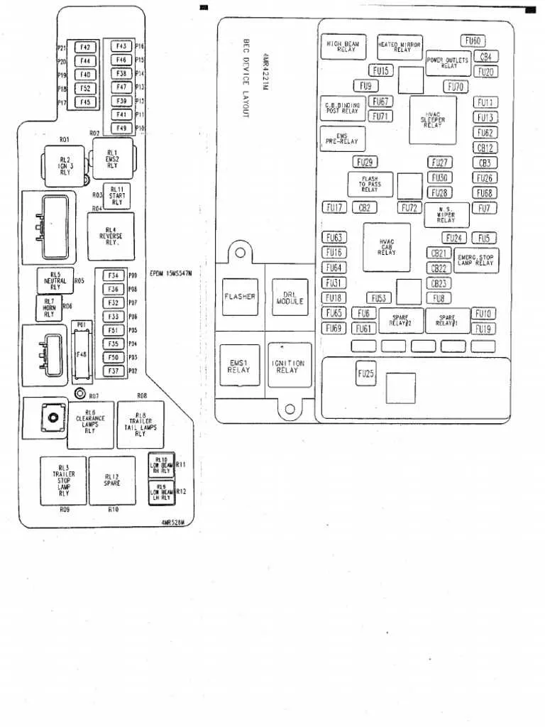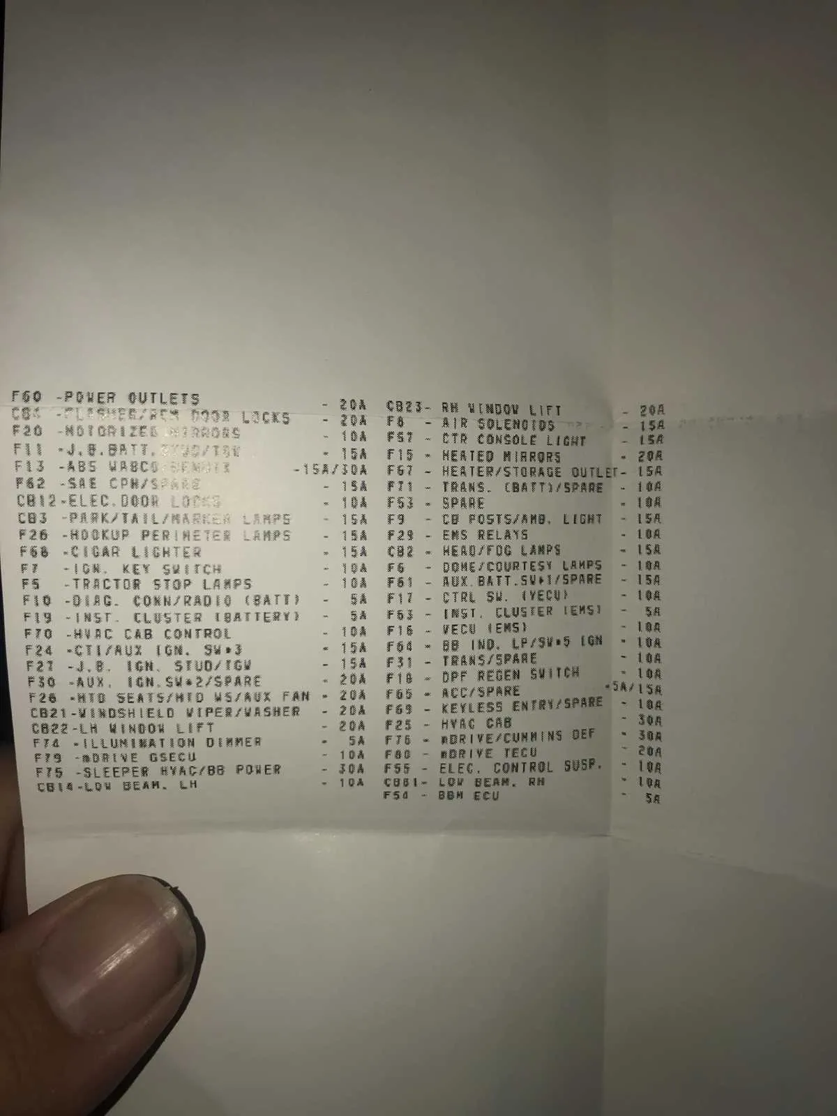
To easily locate and troubleshoot issues within the truck’s electrical network, refer to the detailed schematic for the power distribution components. This layout will guide you through the positioning and function of each relay and circuit protector, ensuring a swift diagnosis and repair process.
Locate the Primary Distribution Panel: It is typically found under the driver’s side dashboard or near the engine compartment. Check the vehicle manual for the precise position in your model. This panel is essential for managing the vehicle’s electrical supply to various systems, including lights, air conditioning, and engine management.
Understanding the Relay Configuration: Each relay corresponds to a specific circuit within the vehicle. By cross-referencing the layout with the vehicle’s electrical components, you can identify which relay powers the respective device. Replace any faulty relays to prevent further electrical malfunctions.
Labeling and Circuit Identification: Ensure each circuit is properly labeled on the schematic. Mislabeling can lead to confusion during repairs, so verify all connections are accurate and easy to trace. This organization will save time and reduce the risk of electrical issues in the future.
Regular inspection and understanding of the power distribution network will help maintain the functionality of your truck’s essential systems. Keep this reference handy for troubleshooting and repairs.
Electrical System Layout Guide

For proper troubleshooting and maintenance, refer to the detailed layout of the vehicle’s electrical components. Ensure you identify the correct location for each relay, circuit, and terminal.
- Locate the primary electrical panel, typically under the dashboard or near the engine compartment.
- Check the labels on each section, which correspond to various systems such as lighting, air conditioning, and engine control.
- Verify each connection for compatibility with the power requirements of the specific system.
Refer to the pinout for each terminal to avoid issues like blown circuits or intermittent power loss. Pay close attention to the power ratings and wire sizes to ensure consistent performance.
- The main terminal block usually manages higher power loads like the ignition system and alternator.
- Auxiliary sections handle lower power circuits, including sensors and interior accessories.
Use a multimeter to check for continuity and verify if any wiring issues exist. Replace any faulty relays and connectors to ensure reliable operation.
Understanding the Layout of a Mack Fuse Box

Start by identifying the location of the electrical components within the vehicle. The main control units are often placed near the driver’s side or under the dashboard, depending on the model. Check the access panel to ensure all connections are clearly marked.
Use the manual for precise identification of each circuit. Electrical systems are typically organized into sections such as lighting, engine control, and safety. Ensuring you follow the correct order when inspecting each section will save time during maintenance.
Make sure to note the amperage rating of each relay and switch. Overloading can lead to system failures or even damage components. Labeling each part with its function (e.g., horn, air conditioning) helps with troubleshooting.
Pay attention to the layout of individual components. A well-structured unit often has dedicated spaces for key elements such as ignition, brake lights, and other essential functions. Verify that no wires are frayed or loose, as this could cause malfunction or a short circuit.
When replacing any part, use the recommended specifications from the manufacturer. Using incorrect parts can lead to further issues down the line.
Common Fuse Box Issues and How to Diagnose Them
Start by checking for burnt terminals or melted plastic near relays and mini-blades–thermal damage often indicates overloaded circuits or poor connections. Use a multimeter to verify continuity across each slot; zero resistance means the link is intact, while infinite resistance signals a blown element.
Inspect the underside for corrosion on contact points, especially if water ingress is suspected. Green or white residue suggests oxidation, which increases resistance and causes intermittent faults. Clean affected areas with electrical contact cleaner and a soft brush, then dry thoroughly before reassembly.
If certain components like headlights or HVAC fans intermittently fail, probe the circuit directly from the rear of the connector while actuating the switch. Voltage drop greater than 0.3V may point to internal fatigue or poor crimping inside the distribution unit.
For repeat failures of the same slot, trace upstream for shorts or high current draw. Measure amperage using a clamp meter and compare against circuit specs–excess current indicates downstream device malfunction or incorrect load matching.
Do not rely solely on visual inspection. Hairline cracks in the plastic housing or micro-fractures in solder joints can only be identified with magnification or thermal imaging. Replace modules with signs of arcing or internal delamination.
Replacing Fuses in a Mack Fuse Box: Step-by-Step Guide

Disconnect the vehicle’s battery before accessing any electrical panel to eliminate the risk of shorts or injury.
Use a flathead screwdriver to open the protective cover located beneath the dashboard or behind the driver’s side kick panel, depending on the model.
Identify the burnt element by checking for a broken filament or discoloration; confirm with a multimeter set to continuity mode.
Refer to the amperage printed on the damaged piece–never substitute it with one rated higher, as this can cause wire insulation to melt under load.
Remove the faulty component using plastic pullers or insulated tweezers to avoid damaging adjacent connectors.
Insert a replacement with matching specifications directly into the correct slot, ensuring it clicks firmly into place.
Reconnect the battery and turn the ignition to the accessory position. Test the relevant system (lights, horn, HVAC, etc.) to verify proper restoration of function.
Close the access panel securely to prevent moisture ingress and vibration-related loosening.