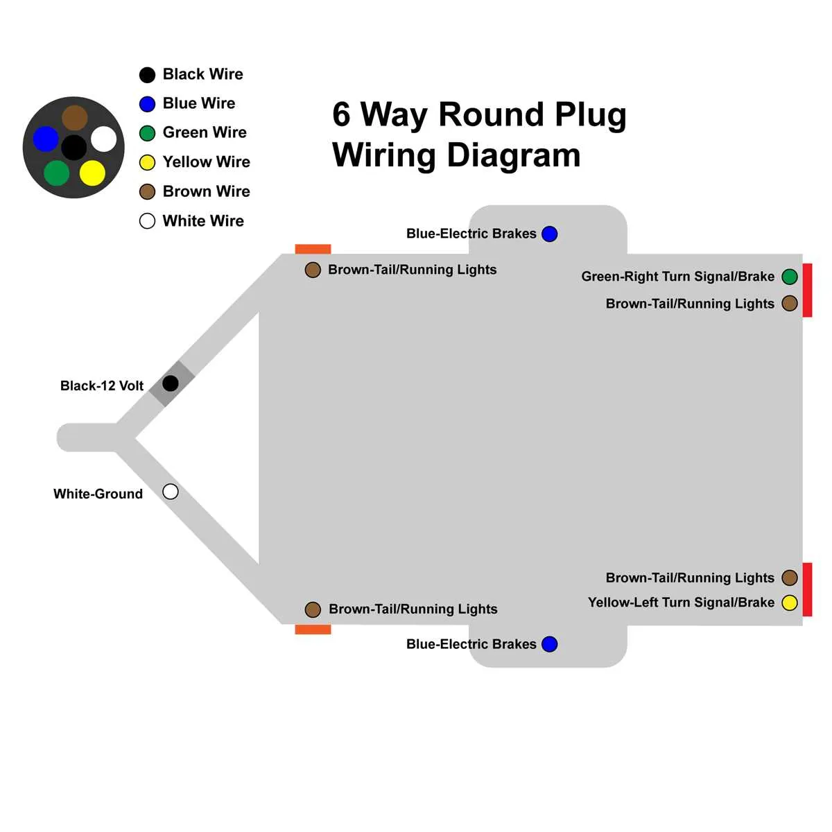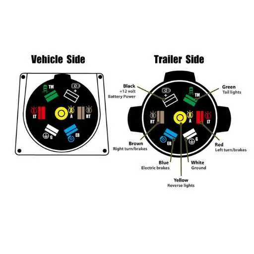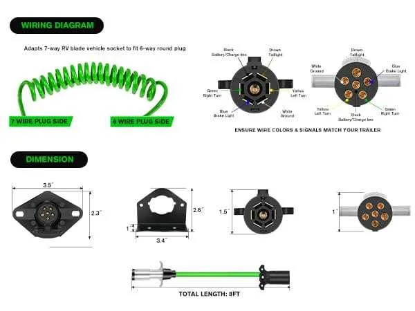
If you’re working with a six-wire connection system for your vehicle and trailer, it’s essential to understand the proper configuration. The six-circuit arrangement allows for safe and reliable communication between both units, ensuring lights, signals, and other functions operate as intended. The correct positioning and use of each wire prevent common issues like short circuits or malfunctioning systems.
Important connections include: a dedicated ground wire, brake lights, turn signals, and running lights. Each of these plays a critical role in maintaining visibility and safety on the road. Improper connections can lead to electrical failures, such as one light flickering or an entire system going out.
Ensure the following: a solid ground connection, secure splices, and avoid using incorrect wire gauges. Also, check for corrosion or wear that could degrade the functionality of each connection over time. Paying attention to wire routing and ensuring they are properly insulated will protect against external elements like moisture.
Lastly, remember that wire color coding is standardized across most setups, which simplifies the installation process. However, always double-check your connections with a voltmeter to confirm that everything is correctly aligned.
6 Pin Electrical Connector Setup
For proper connection between vehicles and towed units, each connector needs to follow the correct wire arrangement. The standard configuration for a six-terminal connector involves the following setup:
1. Terminal 1: Typically used for the ground connection, ensuring the proper grounding of electrical components. This is crucial for the safety of both the towing vehicle and the towed unit.
2. Terminal 2: This one is generally reserved for the left turn signal or indicator light. It ensures that the turn signal from the towing vehicle is communicated to the towed unit accurately.
3. Terminal 3: Designed for the right turn signal, this connection is responsible for transmitting the right indicator signal from the vehicle to the towed unit.
4. Terminal 4: This terminal is connected to the tail lights of the towed unit, allowing both the vehicle and the towed unit’s rear lights to work in sync, enhancing visibility on the road.
5. Terminal 5: Often allocated for the brake light circuit, this connection ensures that when the towing vehicle’s brake lights are activated, the towed unit’s brakes are also signaled correctly.
6. Terminal 6: Commonly used for the auxiliary power supply, this terminal provides a constant 12V power source to the towed unit. It is typically used to power brakes, chargers, or auxiliary systems within the towed vehicle.
Ensure each connection is tightly secured and that the wiring is free of any cuts or damage. Proper maintenance and regular inspection of the connectors can prevent electrical failures during use.
How to Identify the Correct Pins for Each Function in a 6 Pin Connector

To correctly map functions to each terminal in a 6-pin connector, follow these specific guidelines:
- Terminal 1: Typically used for the ground connection, ensuring a safe return path for electrical currents.
- Terminal 2: Often designated for the left-hand indicator, signaling left turns or lane changes.
- Terminal 3: Powers the right-hand indicator, supporting the lighting system for right turns.
- Terminal 4: Generally connected to the tail light, responsible for the rear-end illumination when the vehicle is in operation.
- Terminal 5: Used for the brake light, activating when the vehicle’s brakes are applied.
- Terminal 6: Reserved for additional functions such as reverse lights or auxiliary power, depending on the system’s setup.
Ensure that each wire is correctly matched to its respective function. Double-check the connections using a multimeter to verify continuity, and always follow manufacturer recommendations for color coding, as it may vary across different systems.
Step-by-Step Guide to Wiring a 6 Pin Connector for Towing

Start by gathering the necessary tools: wire stripper, crimping tool, electrical tape, and a suitable connector kit. Ensure you have a wiring harness that matches your vehicle’s and trailer’s electrical systems.
1. First, identify the six required connections on the connector. Typically, these include a ground, brake lights, tail lights, turn signals, reverse lights, and a 12V power supply.
2. Prepare your cables: cut to the required length for each connection, strip about 1 inch of insulation from each end to ensure proper contact.
3. Attach the ground wire to the designated terminal. This wire should always be the first to be secured and is typically black or white.
4. Next, connect the brake light and tail light wires. These will be linked to separate terminals, often marked for clear identification.
5. Secure the turn signal wires to their respective terminals. Usually, the left signal is marked as yellow, and the right signal as green.
6. For reverse lighting, use the blue or purple wire and attach it to the corresponding terminal. This is essential for proper reversing illumination.
7. Finally, connect the 12V power supply. This wire is often heavier gauge and may be marked in red. Make sure it is firmly attached to the correct terminal for consistent power transfer.
| Connection | Wire Color | Terminal Function |
|---|---|---|
| Ground | Black or White | Ground connection |
| Brake Lights | Red | Brake light circuit |
| Tail Lights | Brown | Tail light circuit |
| Left Turn Signal | Yellow | Left turn signal |
| Right Turn Signal | Green | Right turn signal |
| Reverse Lights | Blue or Purple | Reverse light circuit |
| 12V Power | Red | 12V power supply |
After making all the connections, ensure each wire is securely crimped and insulated with electrical tape where necessary. Test the connections with the towing vehicle before use to confirm functionality.
Common Mistakes and Troubleshooting Tips
Incorrect connections are a frequent cause of malfunction. Double-check that each wire is securely attached to the correct terminal. Misplaced connections can lead to loss of signals or improper functioning of lights and other components.
Reverse polarity can cause blown fuses or malfunctioning electronics. Ensure the positive and negative wires are connected properly, especially for the electrical circuit that powers lights and brake systems.
Damaged or frayed cables are a common issue, especially when exposed to wear and tear. Inspect the cable insulation for any cracks or cuts, and replace any damaged sections immediately to avoid short circuits or poor contact.
Loose terminals can cause intermittent problems with electrical flow. Tighten any loose connections and use a wrench to secure them. Additionally, check for corrosion buildup around metal parts, which can impair the signal.
Using incorrect gauge wire can reduce performance. Always use the appropriate gauge based on the load requirements to ensure optimal power flow and prevent overheating.
Improper grounding is a major cause of electrical issues. Make sure the ground wire is properly connected to the frame, ensuring a stable and uninterrupted signal for all components.
Test your setup before fully relying on it. Use a multimeter to verify that all connections are functioning correctly and that no voltage fluctuations are present in critical systems.
Waterproofing is vital for avoiding electrical faults. Ensure that all connectors are sealed against moisture, especially in environments where the setup may be exposed to rain or high humidity.