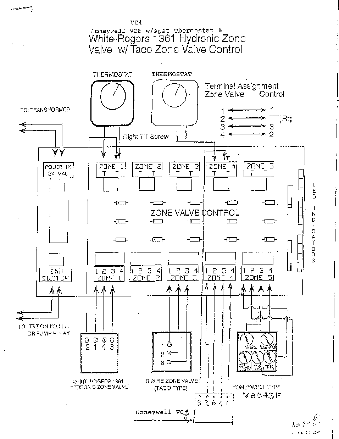
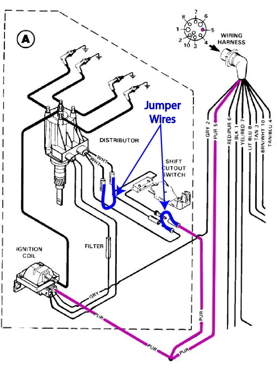
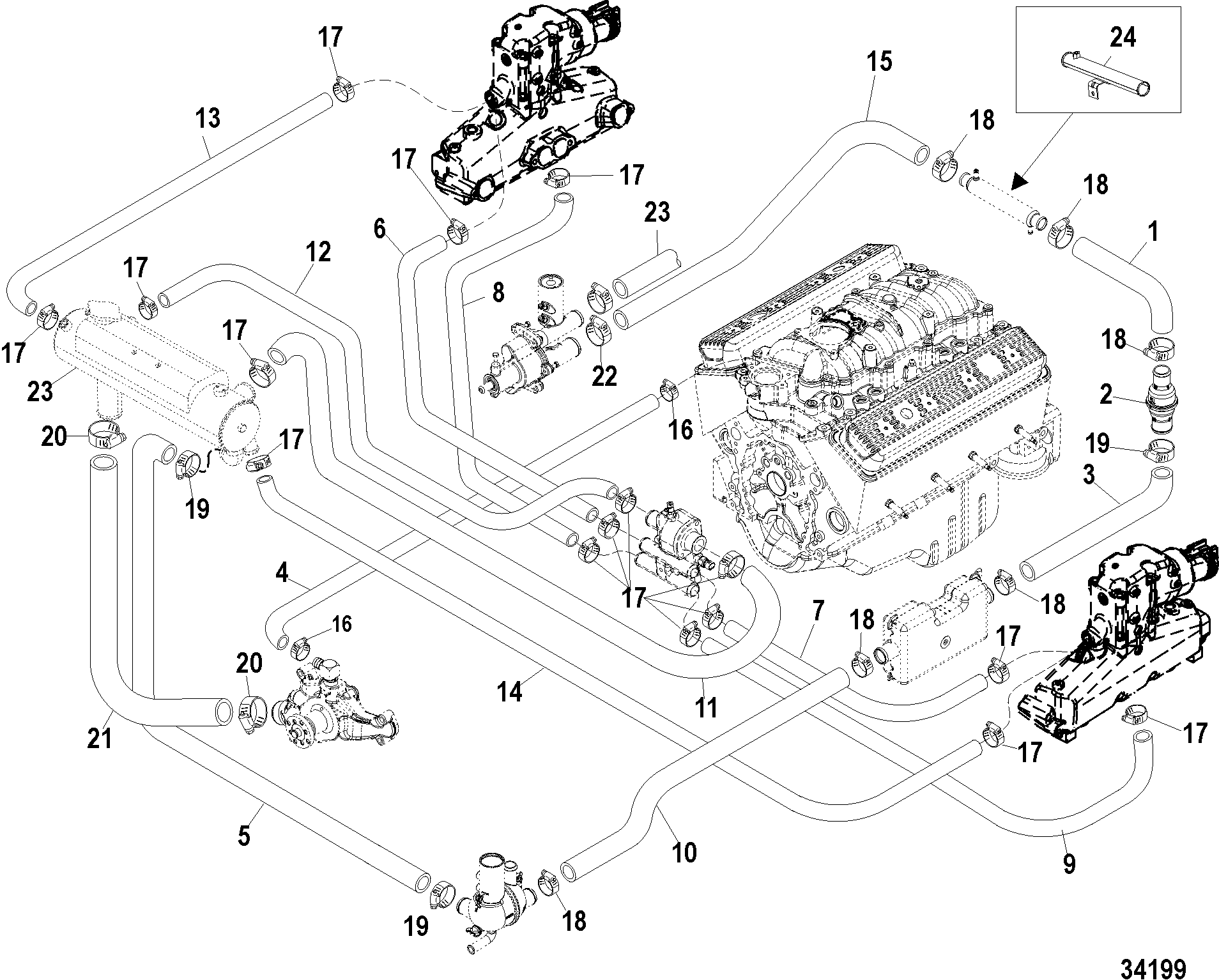
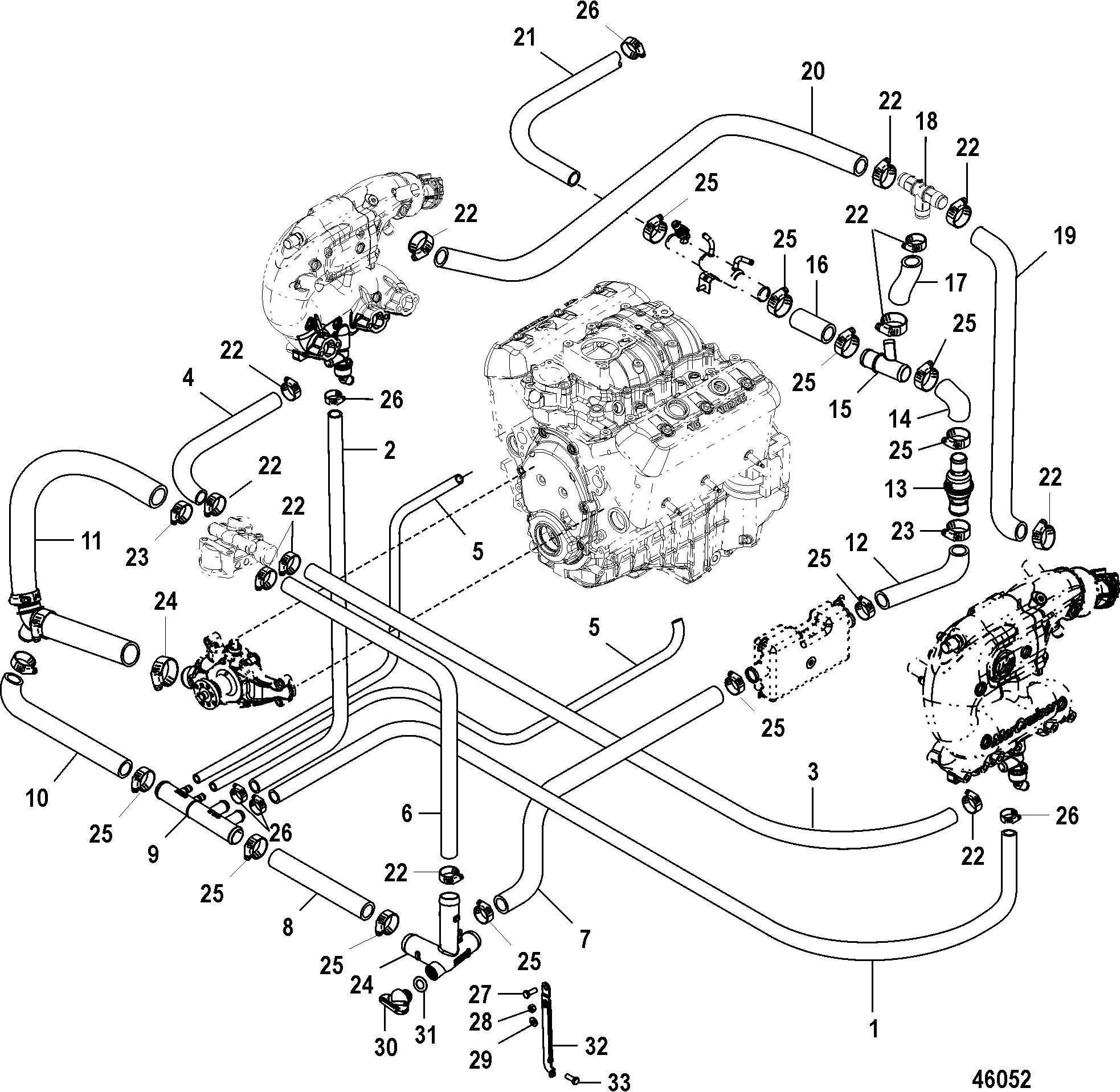
Cooling System Flow Diagram.
6A – 7 When flushing cooling system with boat out of 3. If thermostat is suspected of producing insuffi- cient engine temperature, check thermostat for . Mercury Marine for this model MerCruiser engine.
To. Cooling system flushing procedures are provided in Chapter Four.
Drain and MerCruiser engines may also be equipped with a . Reverse Steps of Removal to complete installation.
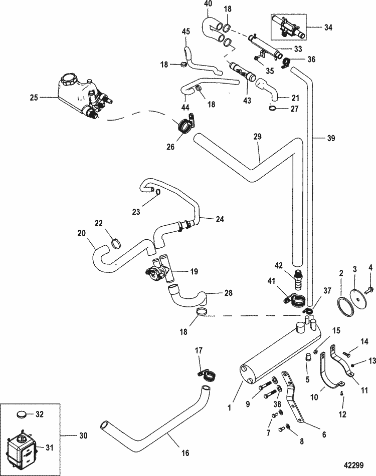
.. cooling system flow diagram (Figures ) and. MerCruiser # 26 GM 4 Cylinder cid (L) ..
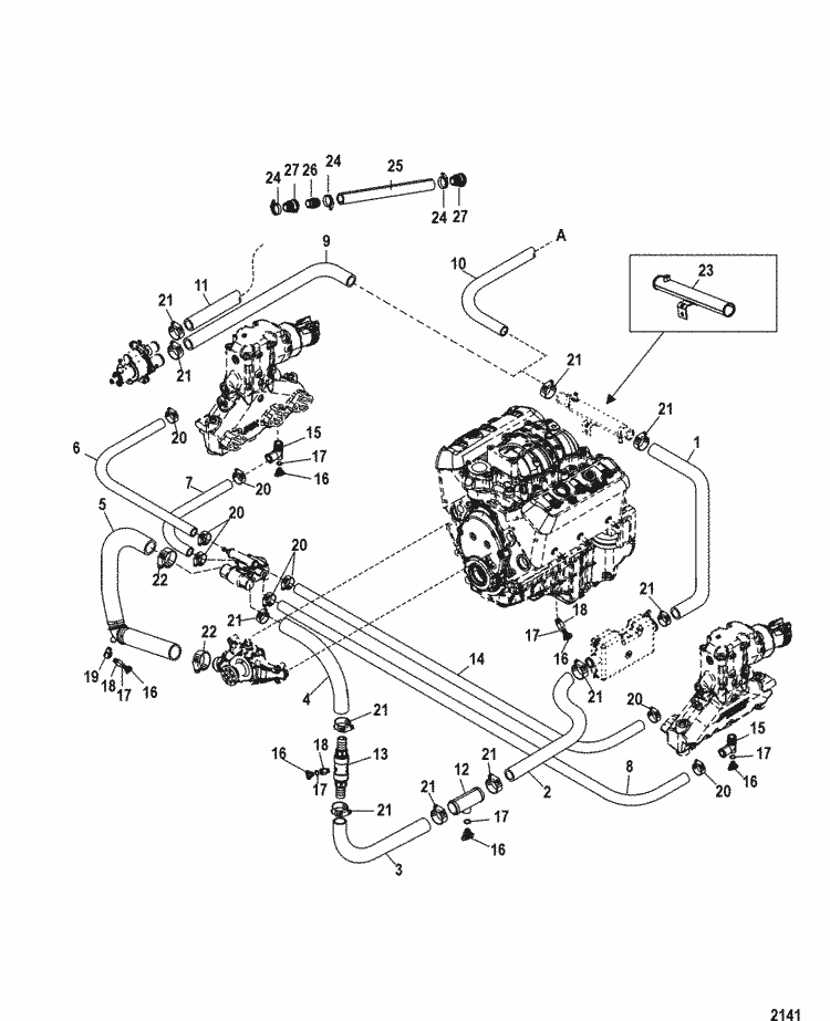
Closed Cooling System Pressure Cap Clean, inspect and test. maximum 60/40 (60% antifreeze, 40% water) Worn pump impeller Refer to water flow diagram for engine type being serviced.
All about marine salt water cooling systems, impeller, heat exchanger, salt water pump- Updated
Closed Cooling System for Mercruiser (l Alpha One) Engine Reference numbers in this diagram can be found in a light blue row below — scroll down to . Fits MCM/MIE L, L, L & L MPI with 1 or 3 point drain system. systems.
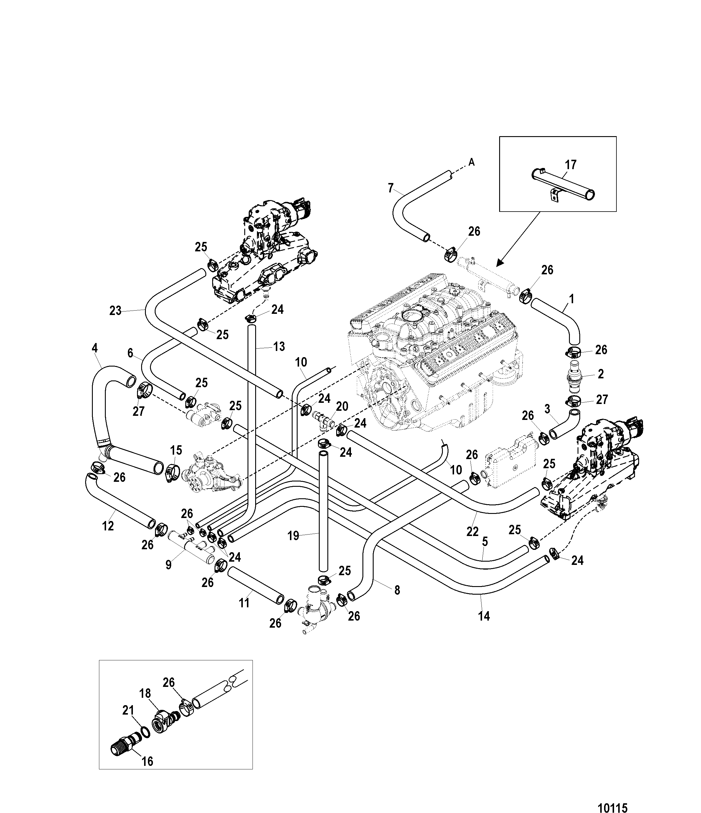
MERCRUISER® COOLING SYSTEM. Not all parts listed are available for the.low cooling system to fill completely.
Cooling sys-tem is full when water is discharged through the propeller. Do not use full tap water pressure.
4. Place remote control in NEUTRAL, idle speed position and start engine. Operate engine at idle speed, in NEUTRAL, for about 10 minutes, or un-til discharge water is clear.
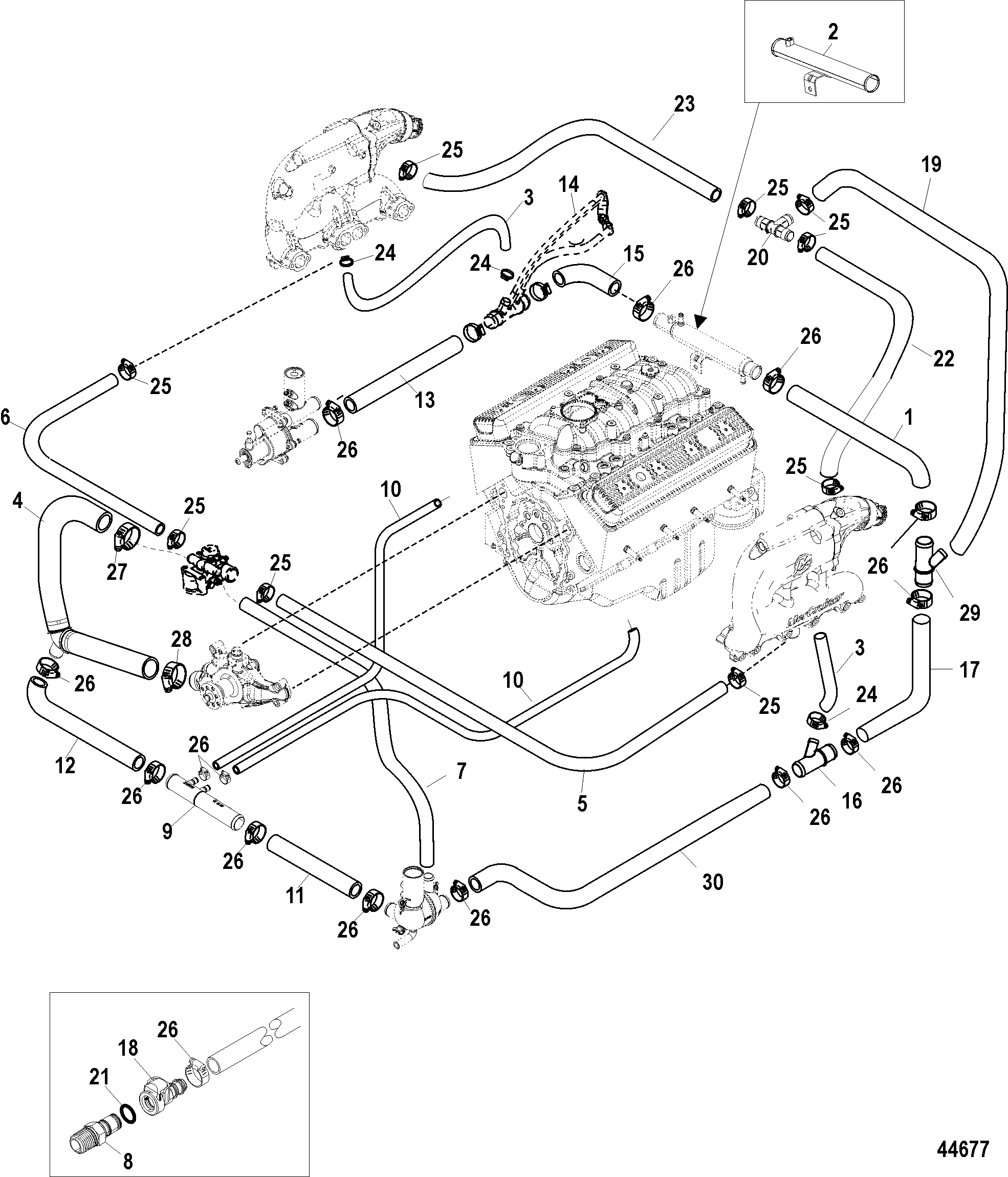
Watch temperature. May 19, · Mercruiser Cooling System Diagram Rachel Savage.
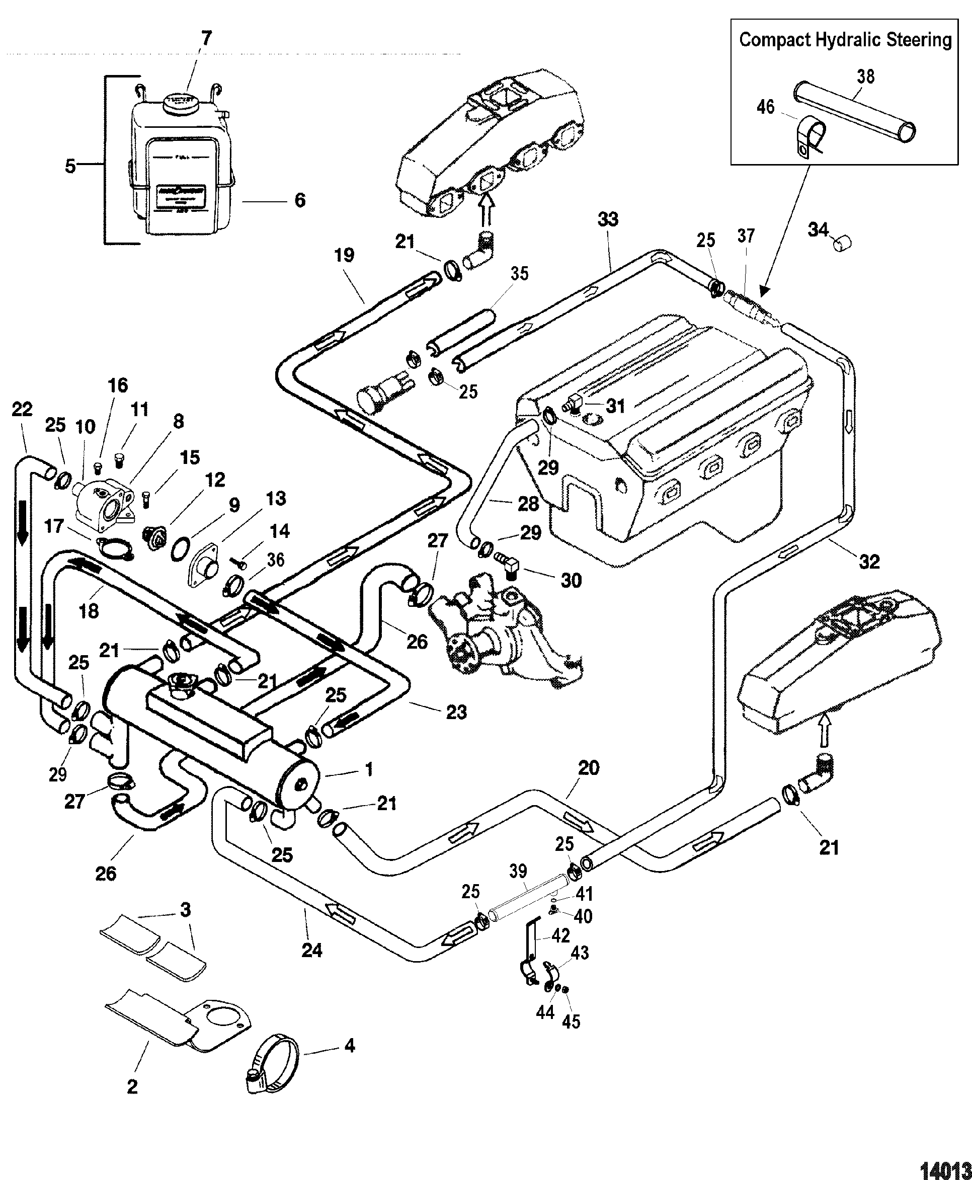
Loading Unsubscribe from Rachel Savage? Mercruiser overheating issues solution – Duration: darexg 11, views. MERCRUISER® COOLING SYSTEM MERCRUISER WATER PUMPS – ENGINE WATER CIRCULATING PUMP Fits MCM Vazer WATER CIRCULATING PUMP Bi‑Directional Fits GM 4 cyl.
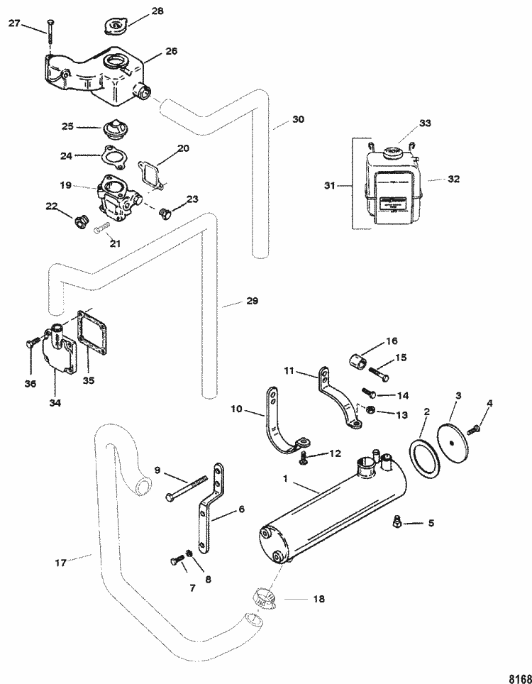
& in‑line 6 cyl. T99 Bi‑Directional Fits MCM L MPI engines WATER CIRCULATING PUMP Fits MCM L engines (s/n 1A and up) . Cooling Flow Diagram: Therefore referencing the above flow diagram we want to point out a few of the following Mercruiser specific features: Reference Item “C” Check Valve – This is a patented feature offered by Mercruiser.
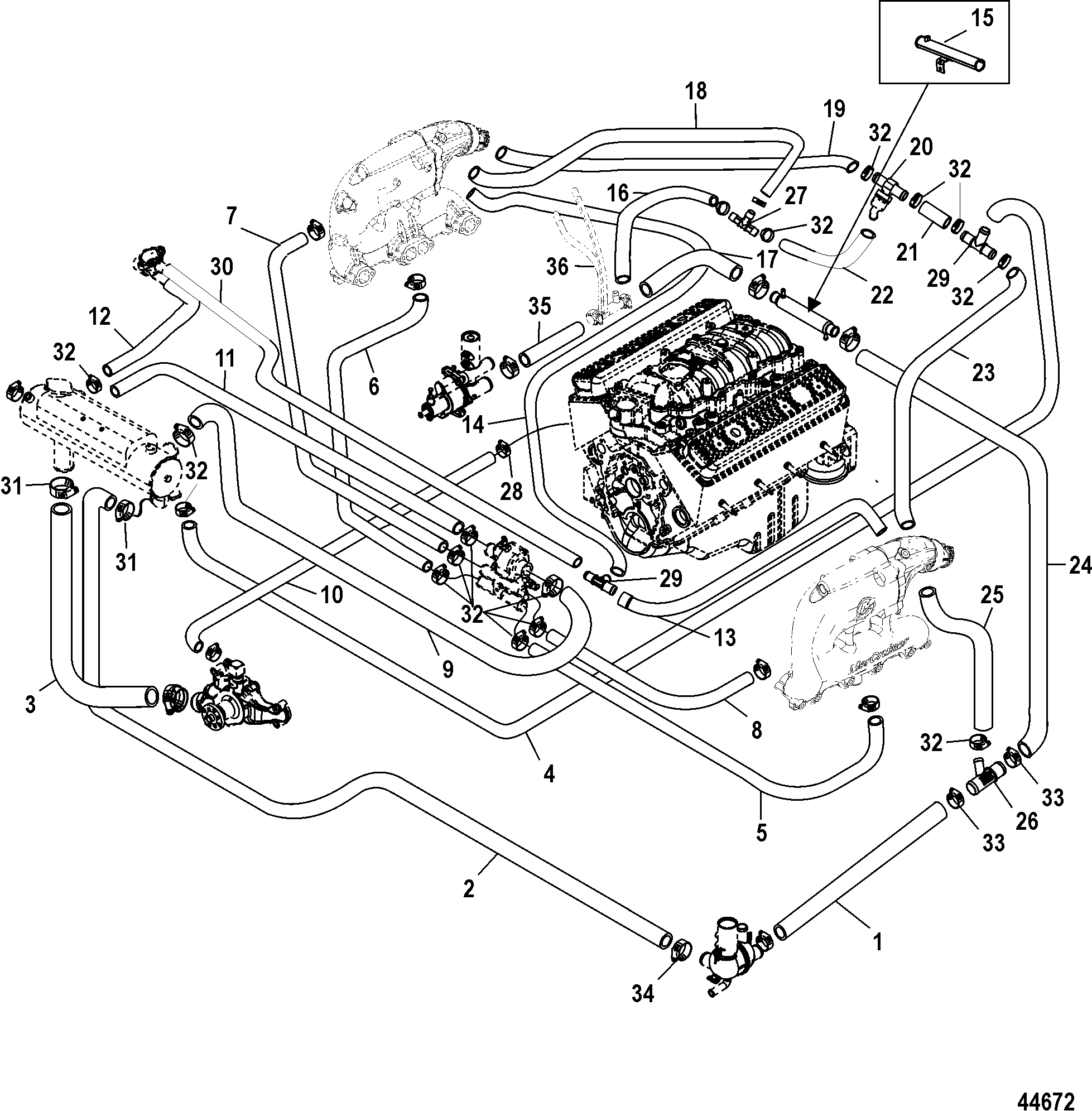
Jun 06, · Re: Mercruiser I/O engine fresh cooling system 1You will have to remove to water pump from the outdrive. Your motors water pump will be used with the new cooling system.
2 yes,Your car has a closed cooling system look at it that way. 3 If you are running on fresh water,none.STANDARD COOLING SYSTEM – Mercruiser L [ALPHA] TS | Crowley MarineMercruiser Closed Cooling System Flow Diagram | schematron.org