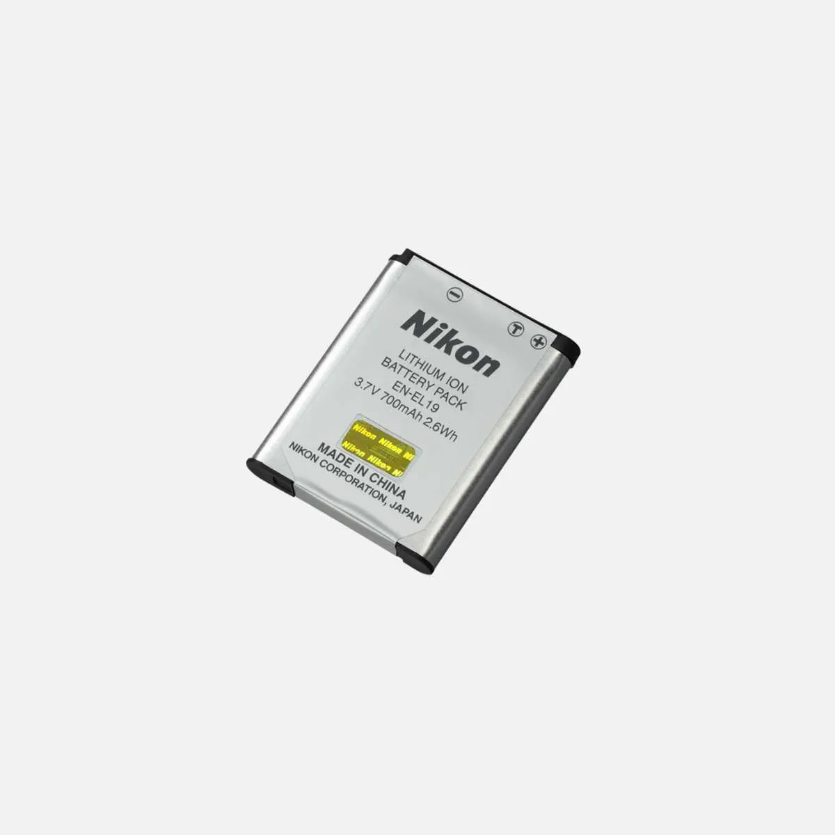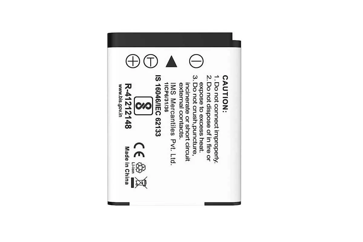
For optimal performance and repair of Nikon’s rechargeable energy source, it’s crucial to have a clear understanding of its internal configuration. A detailed representation of its electrical components and connections is essential for anyone working with or maintaining these units.
Proper disassembly starts with identifying the critical nodes, such as the power input terminals, the connection points to the cells, and the protective circuit components. Understanding how these sections interact ensures safe handling and effective troubleshooting when needed.
When approaching repairs, focus on the current path from the input to the energy storage elements. Ensure continuity between cells and monitor for any disconnections or faults in the voltage regulation components that might disrupt charging or discharging cycles.
To minimize risk, always check the integrity of the protection circuit, which safeguards against overcharging, overcurrent, and thermal issues. Familiarize yourself with the placement of key resistors, transistors, and diodes that control these protective mechanisms.
Power Unit Wiring and Circuit Layout
For proper understanding and maintenance of the power unit, refer to the electrical connections, component placements, and current flow outlined in the design. The structure includes multiple cells connected in series to deliver consistent voltage output. Each cell is equipped with protection circuitry to prevent overcharge, over-discharge, and short circuits.
The connections between individual cells are managed through a series of conductive tracks and protective components. These tracks should be inspected for signs of wear or corrosion, as any irregularity can lead to power failure or malfunction. Additionally, the interface points for connecting to the charging and power supply circuits are clearly marked, allowing for safe and efficient recharging.
The monitoring system, integrated into the power unit, constantly checks the charge level, ensuring balanced distribution across all cells. In case of imbalance, an automatic corrective action is triggered to prevent damage. Pay attention to the sensor wiring and ensure that all connectors are secure for accurate readings.
Internal fuses provide a safety net by disconnecting the unit in case of excessive current flow. It’s critical to verify that these fuses are intact and functional during inspections. Damaged fuses should be replaced immediately to avoid potential hazards.
For optimal performance, the unit should be stored in a cool, dry environment, avoiding excessive heat or moisture, which could degrade the internal components. Regular maintenance checks should include visual inspections of the electrical components and testing of voltage output under load conditions to ensure reliable operation.
Identifying Key Components in the EN-EL 19 Power Cell Layout

When analyzing the electrical configuration of the EN-EL 19 unit, focus on the following primary elements:
1. Voltage Regulation Circuit: This section ensures stable output by controlling fluctuations. It typically includes a voltage regulator IC and associated capacitors, which are crucial for smooth power delivery.
2. Protection Circuit Module (PCM): Vital for ensuring safety, this component prevents overcharging, overdischarge, and short circuits. It’s typically composed of MOSFETs, resistors, and temperature sensors.
3. Charging and Discharging Contacts: These conductive points facilitate the connection between the power source and the internal cells. Look for high-quality metal pins that ensure minimal resistance during charge cycles.
4. Energy Storage Cells: The cells are generally lithium-ion types, arranged in a specific configuration. Their specifications are critical for ensuring the correct energy density and operational lifespan.
5. Thermal Management System: Integrated thermistors and heat sinks regulate temperature. Overheating prevention is a key aspect of the unit’s longevity and efficiency.
6. Data Communication Interface: Some designs include a communication protocol that allows the device to exchange status information. Identifying the connection points for this data line can help diagnose performance issues.
Recognizing these components and understanding their interconnections will assist in troubleshooting, maintenance, and ensuring proper operation of the unit.
How to Read and Interpret the Circuit of the EN-EL 19
When examining the electrical layout of the EN-EL 19, focus on the core components and their connections to understand its operation. Follow these key steps to efficiently interpret the wiring and element arrangement:
- Identify the main connections – Locate the input and output terminals. These are critical as they define where energy enters and exits the system.
- Trace the conductors – Follow the paths marked with lines that indicate wire routes. Pay attention to any junctions, where multiple paths converge, which could affect energy flow.
- Recognize component symbols – Understand the representations of resistors, capacitors, diodes, and transistors. Each has a standard symbol, and knowing these will allow you to interpret the functionality of each element.
- Examine polarity – Some elements, like diodes and electrolytic capacitors, have specific polarity. Ensure the orientation of these components is consistent with the design to avoid malfunction.
- Measure voltage and current – Identify where voltage and current measurements are indicated in the circuit. This helps in evaluating if the power distribution is balanced across components.
- Understand the ground connection – The ground is the reference point for all voltage measurements. Identify how it is linked throughout the system, ensuring the proper flow of electricity.
Once familiar with these components and their relationships, you’ll have a clearer view of how the system operates and how each part contributes to its overall function.
Common Issues and Troubleshooting Tips for the EN-EL 19 Power Circuit

If the device fails to power on or show signs of charging, the first thing to check is the connection between the terminals and the power supply. Ensure that there is no corrosion or debris disrupting the flow of energy. A multimeter can be used to check the voltage at the output terminals, which should match the expected values indicated by the manufacturer. If the reading is significantly lower, it suggests an issue with the internal components, such as a faulty cell or poor soldering joints.
Another common issue is overheating. If excessive heat is noticed during charging or operation, check for signs of short circuits or damaged conductors within the system. Inspect the protective components and replace any damaged fuses or resistors. In some cases, overheating may also occur due to high resistance connections, so ensure that all connectors are firmly in place and free of any oxidation.
If the power unit discharges too quickly or fails to hold a charge, the issue could lie within the capacity of the individual cells. Over time, cells degrade and lose their ability to store energy efficiently. Testing each cell for proper voltage and capacity can help identify if any individual units are failing. In this case, replacing the faulty cells may resolve the issue, although it may be necessary to recalibrate the system to ensure optimal performance after the replacement.
Erratic performance can also be attributed to issues with the charging circuitry. If the charging process is inconsistent, it might be due to a malfunctioning charging controller or issues within the protection circuit. To diagnose this, inspect the charging input circuit for any loose components or failed capacitors that could be preventing proper current regulation. Additionally, make sure that the input voltage matches the required specifications to avoid damaging the circuit.
Lastly, environmental factors such as humidity and extreme temperatures can also negatively affect the internal components. Store and use the unit in a dry, temperature-controlled environment to avoid damage. If the unit has been exposed to moisture, drying out the components thoroughly before use is critical to prevent internal corrosion and malfunctions.