To analyze how forces interact with a system, start by plotting the relationship between position and force. This allows you to visualize the changes within the system as it moves through different states. Begin by identifying key points such as equilibrium positions and turning points where motion reverses or stabilizes.
Next, ensure your graph includes relevant data points that mark the potential for work to be done. Highlight areas where objects are either compressed or stretched, indicating regions of maximum force interaction. These details can be easily calculated by comparing the current system state to its baseline, often referred to as the reference point.
When creating these plots, focus on the areas where the system undergoes transitions. Clearly marking the minimum and maximum values helps clarify how the object will behave under varying conditions. By doing this, you prepare yourself to predict the system’s behavior as external conditions change.
Additionally, practice interpreting these visuals by drawing comparisons to real-world examples. For instance, a simple spring system or a pendulum can serve as practical models for this concept, where similar graphs will help clarify the mechanics behind the changes in force as the object moves.
Tip: Don’t forget to label your axes clearly, ensuring that your graph reflects the most accurate model possible. This practice will help you gain deeper insights into system behavior and improve your predictive analysis skills.
Understanding Reaction Pathways and States

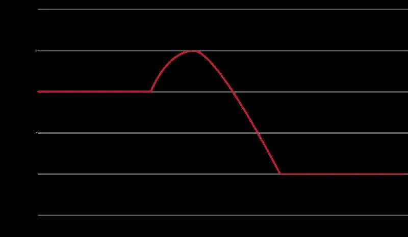
Identify key points in the process, including reactants, transition states, and products. Label the highest point as the activation barrier, which represents the energy required to start the reaction. Below this, mark the initial state with the lowest energy, showing where the reactants begin. The final state should be placed at a lower level if the reaction is exothermic, or higher if endothermic.
Clearly show how the pathway moves from the start to the finish. The shape of the curve is essential to understand the reaction’s progress and how it fluctuates in different stages. The rate-determining step is often located at the peak of the barrier, highlighting the slowest part of the process.
Ensure that the vertical axis reflects the relative stabilities of the different states. The greater the difference between reactants and products, the more energy is released or absorbed. Use distinct labels for each section, such as activation complex or intermediate states, to make the diagram easy to interpret and analyze for clarity.
Focus on accuracy in plotting the heights and positioning of each state. This helps in determining the overall feasibility of the reaction and the nature of the activation barrier in determining the rate of progress.
How to Draw a Reaction Pathway for a Chemical Transformation

Start by identifying the reactants and products of the reaction. Place the starting point on the left and the final state on the right of the graph. Mark the initial value of the system’s state at the reactants level. Then, plot the transition from reactants to products, ensuring to include any intermediate states or activated complexes.
Next, find the peak of the curve, which represents the highest point of the transformation. This is where the system requires the maximum input to proceed. Label this point as the activated complex or transition state. The difference in height between the reactants and this peak indicates the required input for the reaction to occur.
As the system moves towards the products, ensure that the curve slopes downwards if the reaction releases heat. The final level should be placed below the reactant level if the reaction is exothermic, and above if it is endothermic. The difference between the initial and final points reflects the net release or absorption of heat during the process.
To complete the visual, ensure that all transitions are smooth, with no sharp breaks unless depicting an abrupt change in conditions. Label each section of the graph clearly to indicate reactants, products, and the activation barrier, ensuring clarity in presenting the reaction’s profile.
Interpreting the Key Features of a Potential Energy Diagram
To accurately analyze a graph representing the changes in stored work within a system, focus on the following aspects:
- Equilibrium Position: The lowest point on the curve represents a state where the forces are balanced. This indicates the most stable configuration of the system.
- Maximum and Minimum Points: Peaks represent unstable states, while valleys denote stable configurations. The higher the peak, the more unstable the system in that state.
- Transition Regions: The areas between peaks and valleys show how the system moves from one stable state to another. The steeper the slope, the faster the transition occurs.
- Activation Barrier: The height between a valley and an adjacent peak signifies the amount of work needed to move the system from one stable state to another.
- Shape of the Curve: A smooth, curved line suggests gradual changes, while abrupt shifts indicate sharp, fast transitions between states.
Focusing on these features will allow you to determine the relative stability of various system states, as well as the forces driving transitions between them.
Practical Applications in Reaction Kinetics
Understanding the graphical representation of a chemical reaction’s progress is crucial for optimizing reaction rates. A key application of these representations lies in determining the activation barrier, which directly influences the speed of the reaction. By identifying the peak of the curve, one can estimate the minimum input required to initiate the process. This is invaluable when fine-tuning reaction conditions, such as temperature or concentration, to either accelerate or slow down a reaction.
Reaction rate manipulation is one of the primary practical uses. For reactions with a high activation barrier, increasing the temperature or adding a catalyst can lower the threshold, enhancing the reaction rate. Conversely, for processes where slowing the reaction is necessary, reducing temperature or applying inhibitors can raise the barrier, slowing down the overall kinetics.
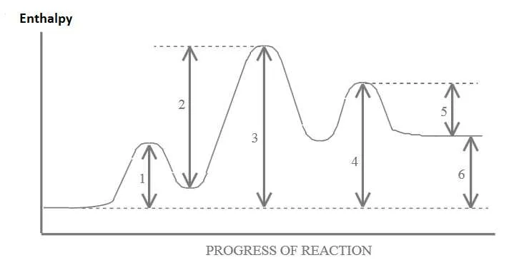
Mechanistic insight can also be gained by analyzing the shapes of these curves. For example, a smooth, gradual ascent to the top of the curve suggests a single-step reaction, while a more complex curve with multiple peaks indicates a multi-step process. This can guide researchers in designing new catalysts or understanding intermediate stages in complex reactions.
Additionally, these visual tools help assess reaction spontaneity by comparing the relative positions of reactants and products. If the products are lower than the reactants, the process is thermodynamically favorable and may proceed more readily, influencing industrial applications like the synthesis of pharmaceuticals or materials.
Overall, mastering these graphical models enables chemists to predict and control the behavior of reactions in both laboratory and industrial settings, optimizing both safety and efficiency.