
Having a pool timer is essential for maintaining a well-regulated swimming pool. It allows you to automate the operation of various pool equipment, such as pumps, heaters, and lights, ensuring they turn on and off at specific times. By using a pool timer, you can save energy, reduce costs, and extend the lifespan of your pool equipment.
Understanding how to properly wire your pool timer is crucial to ensure its correct operation and to prevent any electrical issues. A pool timer typically consists of a time clock, which is the main control unit, and various terminals for connecting the different pool equipment. It is important to refer to the wiring diagram provided by the manufacturer to ensure proper installation.
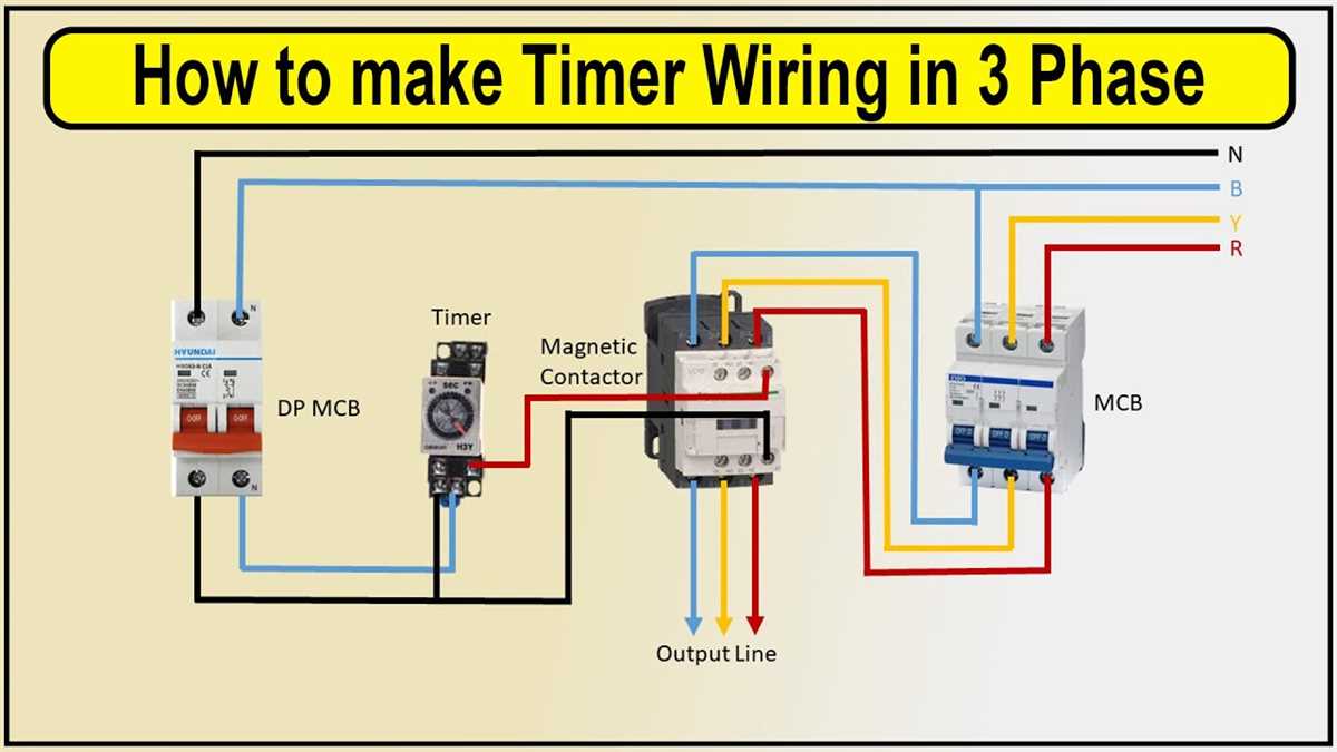
The wiring diagram shows the layout of the terminals on the pool timer and how each piece of equipment should be connected. It identifies the different wires, such as the main power supply, the load wires for the pool equipment, and any additional wires for accessories like a heater or lights. Following the wiring diagram is essential to avoid any potential errors or safety hazards.
Understanding Pool Timer Wiring Diagrams
Pool timer wiring diagrams are essential for properly setting up a pool timer system. They provide a visual representation of how different components of the timer interact and how the wires should be connected. By understanding these diagrams, pool owners and electricians can ensure the timer is wired correctly, which is crucial for the proper functioning of the pool’s heating, filtration, and lighting systems.
When looking at a pool timer wiring diagram, there are several key components to take note of. These include the timer itself, which controls the on/off schedule of the pool’s equipment, such as the pump and heater. The diagram will also show the connections for the power supply, typically from the main electrical panel, as well as any additional devices, such as switches or relays, that may be used to control specific functions.
One important aspect of understanding pool timer wiring diagrams is recognizing the distinction between line voltage and low voltage wiring. Line voltage refers to the standard power supply, typically at 120 or 240 volts, which powers the pool equipment. Low voltage wiring, on the other hand, is used for control signals and is typically at 12 or 24 volts. These two types of wiring will be clearly illustrated in the diagram to ensure proper connections are made.
It is crucial to follow the specific wiring diagram provided by the manufacturer of the pool timer to ensure safe and correct installation. Each timer may have its own unique wiring configuration, so it is essential to refer to the diagram that corresponds to the specific make and model of the timer being used. By following the diagram and understanding the different components and connections, pool owners and electricians can ensure that the timer system functions correctly, allowing for efficient operation of the pool’s equipment and optimal enjoyment of the pool.
Components of a Pool Timer
A pool timer is an essential component of a swimming pool’s electrical system. It controls the timing of various pool equipment, such as pumps, heaters, and lights, ensuring that they operate at specific times and durations. Understanding the components of a pool timer is crucial for proper installation and maintenance.
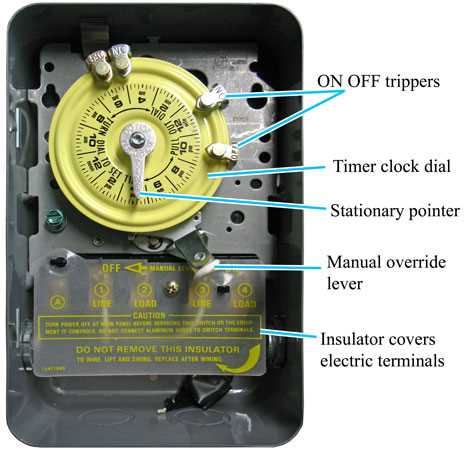
Here are some of the key components that you will commonly find in a pool timer:
- Clock Mechanism: This is the heart of the pool timer, responsible for keeping time and controlling the schedule. It usually consists of a motor and gears that move the clock hands or digital display. The clock mechanism can be set to turn the pool equipment on and off according to the desired schedule.
- Timer Switch: The timer switch is a crucial part of the pool timer, allowing you to set the desired timing for the pool equipment. It typically has dials or buttons that you can adjust to specify when the equipment should turn on or off. The timer switch is connected to the clock mechanism and controls its operation.
- Relays: Relays are electromechanical devices that act as switches, allowing the pool timer to control the power to the various pool equipment. They provide an interface between the low-voltage control signals from the timer switch and the high-voltage power supply of the pool equipment. The relays enable the timer to turn the equipment on and off based on the specified schedule.
- Power Supply: The power supply is responsible for providing the necessary electrical power to the pool timer and the connected equipment. It is usually connected to a standard electrical outlet, and its voltage and current rating should be suitable for the specific pool timer and equipment being used.
- Override Switch: The override switch is a convenient feature that allows you to manually control the pool equipment independently of the timer’s schedule. It is typically a toggle switch that can override the timer’s settings, turning the equipment on or off immediately when needed.
These are the main components you will find in a typical pool timer. Understanding their functions and how they work together is essential for effectively managing and maintaining your pool’s electrical system.
Wiring Basics for Pool Timers
When it comes to pool timers, understanding the wiring basics is essential for proper installation and operation. Pool timers are devices that control the on and off cycles of pool equipment such as pumps, heaters, and lights. They help maintain the desired pool temperature, optimize energy usage, and ensure efficient pool maintenance.
Pool timers typically have a few key components: a power supply, a time clock mechanism, and output terminals for connecting the pool equipment. The power supply provides the necessary electrical current to operate the timer, usually sourced from the main electrical panel. The time clock mechanism is responsible for setting the on and off cycles according to the desired schedule, allowing users to control when the pool equipment operates. The output terminals are where the pool equipment is connected.
When wiring a pool timer, it is important to follow the manufacturer’s instructions and adhere to electrical safety guidelines. It is recommended to use a licensed electrician or a qualified professional to ensure proper installation. Typically, the wiring process involves connecting the power supply wires to the designated terminals on the timer, connecting the pool equipment wires to the appropriate output terminals, and ensuring that all connections are secure and insulated.
Here is a basic wiring diagram for a pool timer:
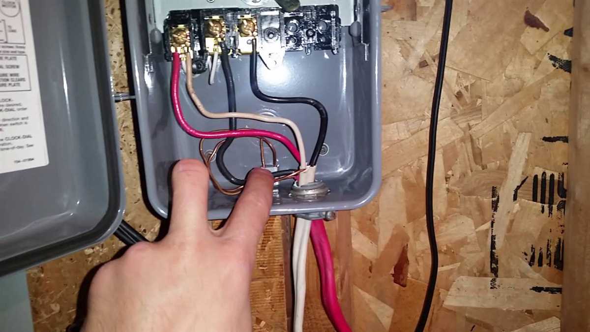
- Connect the incoming power supply wires to the line terminals on the timer.
- Connect the outgoing wires from the pool equipment to the load terminals on the timer.
- Ensure that the ground wires are properly connected to the ground terminal on the timer and to the electrical panel.
- Double-check all connections and tighten any loose screws or terminals.
- Test the timer to ensure it is functioning correctly and following the set schedule.
It is important to note that specific wiring diagrams may vary depending on the type and model of the pool timer being used. Always refer to the manufacturer’s instructions for the most accurate and detailed information.
Common Wiring Configurations for Pool Timers
When installing a pool timer, there are several common wiring configurations that can be used depending on the specific needs and setup of your pool. These configurations determine how the timer interacts with the pool equipment and power supply. Here are a few examples of common wiring configurations for pool timers:
1. Single-Speed Pump Timer

In this configuration, the pool timer is wired to control a single-speed pump. The timer is connected to the power supply and the pump motor. When the timer is set to turn on, it supplies power to the pump, allowing it to operate. When the timer is set to turn off, it cuts off power to the pump, shutting it down. This configuration is commonly used with older pool pumps that do not have variable speed settings.
2. Dual-Speed Pump Timer
For pools with dual-speed pumps, a different wiring configuration is required. The timer is connected to both the high-speed and low-speed settings of the pump. When the timer is set to turn on, it supplies power to the appropriate speed setting, allowing the pump to operate at the desired speed. When the timer is set to turn off, it cuts off power to both speed settings, shutting down the pump completely.
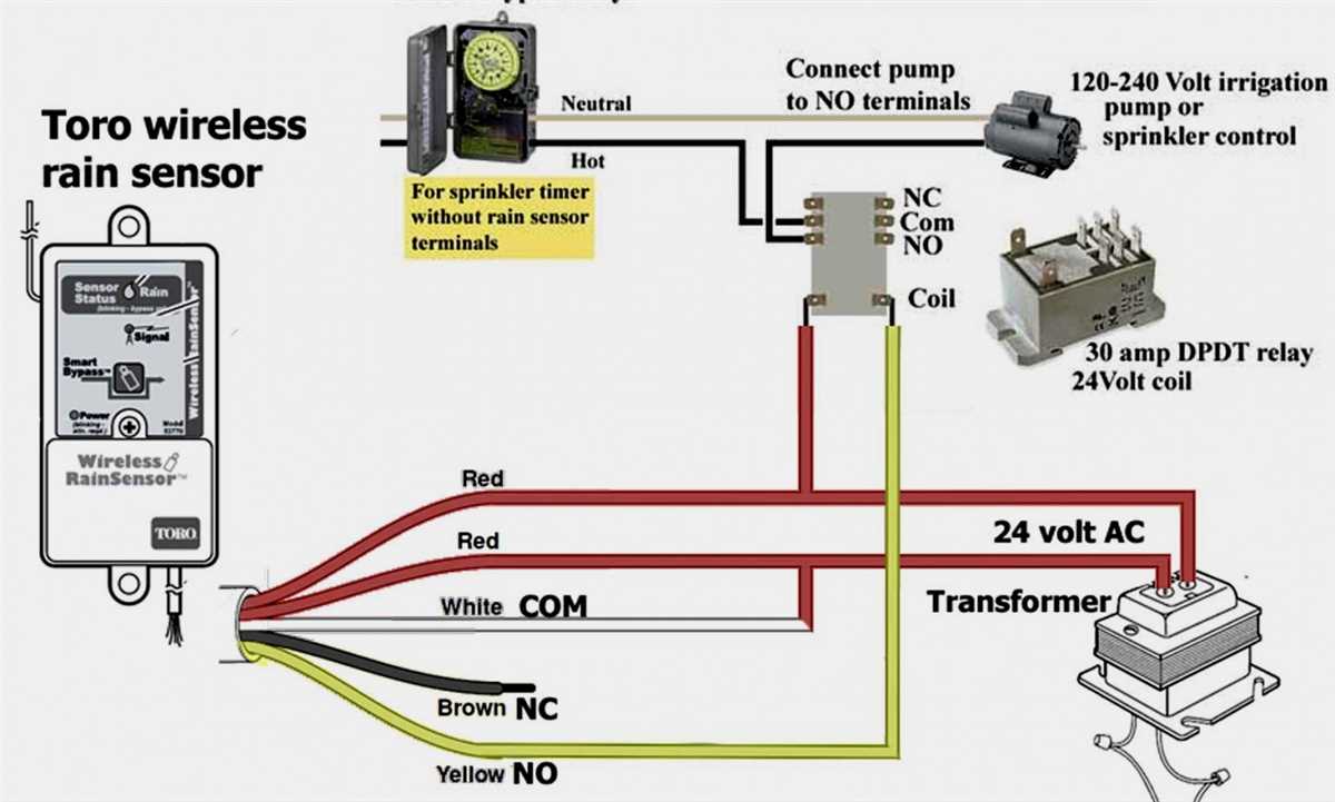
3. Heater and Pump Timer
In pools that have a heater and a pump, a wiring configuration is needed to control both devices. The timer is connected to the power supply, the pump motor, and the heater. When the timer is set to turn on, it supplies power to both the pump and the heater, allowing them to operate. When the timer is set to turn off, it cuts off power to both devices, shutting them down.
4. Multiple Equipment Timer
Sometimes, pools have multiple pieces of equipment that need to be controlled by the timer, such as a pump, heater, and lights. In this type of configuration, the timer is connected to all the necessary equipment, allowing them to be controlled simultaneously. The timer can be set to turn on or off all the connected equipment at the same time or individually, depending on your needs.
These are just a few examples of the common wiring configurations used for pool timers. The specific configuration you choose will depend on the equipment you have in your pool and your desired control options. It is always recommended to consult the manufacturer’s instructions or a professional electrician when installing a pool timer to ensure proper wiring and safe operation.
Troubleshooting Pool Timer Wiring Issues
Pool timers are used to control the operation of various components in a swimming pool, such as pumps, heaters, and lights. However, like any electrical system, pool timer wiring can sometimes malfunction or encounter issues. In this section, we will discuss some common troubleshooting steps for pool timer wiring problems.
1. Check the power supply
The first step in troubleshooting pool timer wiring issues is to check the power supply. Make sure that the circuit breaker or fuse controlling the pool timer is in the “On” position. If the circuit breaker has tripped or the fuse has blown, reset or replace them accordingly.
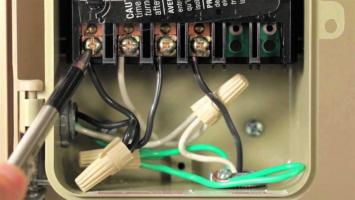
2. Inspect the wiring connections
Next, carefully inspect the wiring connections in the pool timer. Look for any loose or disconnected wires, burnt or damaged insulation, or corroded terminals. If you find any issues, tighten loose connections, repair or replace damaged wires, and clean corroded terminals.
Also, ensure that the wires are properly connected to the appropriate terminals in the pool timer. Refer to the wiring diagram or instructions provided with the timer to ensure correct connection.
3. Test the timer switch
If the power supply and wiring connections are all in good condition, the issue may be with the timer switch itself. Use a multimeter to test the continuity of the timer switch. Set the multimeter to the continuity or resistance mode, and check for continuity between the switch terminals in different switch positions. If there is no continuity or inconsistent readings, the timer switch may be faulty and needs to be replaced.
4. Consult a professional
If you have followed all the troubleshooting steps and are still unable to resolve the issue with your pool timer wiring, it is advisable to consult a professional electrician or pool technician. They have the expertise and knowledge to diagnose and repair complex wiring issues.
Overall, troubleshooting pool timer wiring issues requires careful inspection, testing, and, if necessary, repair or replacement of faulty components. By following these steps, you can efficiently identify and resolve any problems with your pool timer wiring.