For a smooth setup of a 36V electrical system, ensure the connections between each component are precise. Begin by confirming the power source’s polarity to avoid any potential damage. The positive terminal should be connected to the main power line, while the negative terminal links to the ground or return wire.
Choosing the Right Gauge: Use the correct gauge for your cables to prevent overheating or excessive power loss. For a 36V configuration, 12 AWG is typically suitable for short distances, while 10 AWG should be used for longer runs. The thicker the cable, the better the current-carrying capacity, ensuring efficient operation of your system.
Balancing the System: It’s crucial to ensure the load is balanced across the power units. Uneven distribution can cause one unit to discharge faster than others, leading to inefficiency and potential failure. Use a junction box or bus bar to evenly distribute the power to each individual circuit.
Lastly, when dealing with high power setups, always ensure all connections are tightly secured and insulated to prevent any risk of shorts or sparks. Regular inspection and maintenance of these connections are essential to prolong the system’s lifespan and performance.
36V Power System Connection Guide

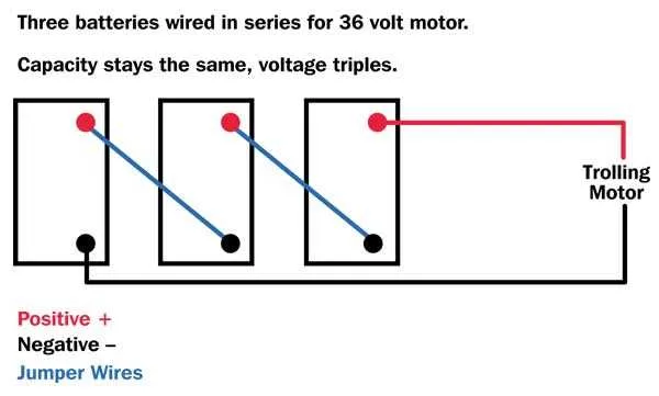
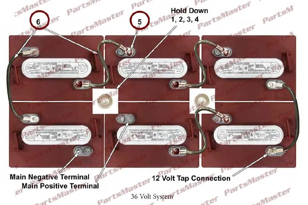
For an efficient 36V power setup, ensure you connect three 12V units in series. Start by linking the positive terminal of the first unit to the negative terminal of the second unit. Similarly, connect the positive terminal of the second unit to the negative terminal of the third unit. The total output can be accessed from the positive terminal of the third unit and the negative terminal of the first one.
To ensure a balanced charge, always verify that each unit has a matching charge level before connecting. Use wires that can handle the required current without overheating. Insulating materials around each connection point will help maintain safety during use.
Pay special attention to polarity: reversing connections can lead to damage or failure of your system. If you are using this setup for an e-bike or solar system, make sure your controller matches the input specifications for a 36V system.
Finally, check for loose connections regularly, as they can cause power loss or short circuits. The overall design should minimize voltage drops across long wires to maintain efficiency.
Understanding the Basic Components of a 36V Power System

The key to an efficient 36V power setup lies in understanding the main elements that make it function properly. Each component plays a crucial role in maintaining performance and safety. Below is an outline of the essential parts of such a system.
- Power Source: This is where energy is stored. Typically, a series of cells are connected to provide the required electrical potential. Ensure the cells are matched in capacity and condition to avoid imbalance.
- Current Path: Properly chosen conductors and connections facilitate the movement of energy between cells and the load. Ensure wire gauge matches the power output to avoid excessive heat buildup.
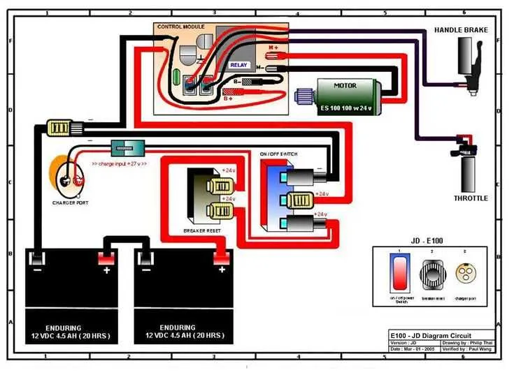
- Control Module: This unit manages power distribution, often incorporating safety features like overcurrent protection. Be sure it can handle the required amperage and integrates well with the system.
- Load: The device that consumes the energy, whether it’s an electric motor or a different tool. Ensure the load matches the system’s output to prevent overloading.
- Charging Mechanism: Typically a dedicated charger designed for the specific setup. Always use the recommended charger for optimal performance and longevity of the system.
For the system to work efficiently, all components need to be compatible and well-maintained. Regular monitoring of each part will ensure longevity and safe operation.
How to Connect Batteries in Series for a 36 Volt Setup
To achieve a 36V configuration, connect three 12V units in series. Start by linking the positive terminal of one unit to the negative terminal of the next. The remaining free terminals will form the output. Ensure the connections are secure and that the units are of equal type and capacity for optimal performance. Use appropriate gauge wire and connectors to handle the current safely.
Begin with the first unit’s positive terminal. Connect it to the negative terminal of the second unit. Then, connect the second unit’s positive terminal to the negative terminal of the third unit. Finally, the positive terminal of the third unit will provide the 36V output, while the negative terminal of the first unit completes the circuit.
Always check for tight, corrosion-free connections, as loose or faulty connections can lead to performance issues or damage. A fuse or breaker on the positive output is also recommended for protection against short circuits or overloads.
Common Mistakes and How to Avoid Them in 36V Systems

Ensure correct polarity when connecting cells. Reversing the positive and negative connections can lead to malfunction or even damage the system. Double-check before powering up your setup.
Use proper gauge cables to avoid overheating or voltage drops. For longer connections, choose thicker cables to ensure efficient power transfer without unnecessary resistance.
Properly balance your cells during setup. Uneven charge levels can cause some cells to overheat while others remain undercharged, leading to inefficiency and potential damage over time. Always monitor the status of each cell regularly.
Avoid overloading the system by ensuring that the current draw does not exceed the rated capacity of your setup. Overloading can cause excessive heat buildup, affecting performance and longevity.
Secure all connections tightly to avoid poor contact points that can lead to sparks or heat buildup. Use high-quality connectors and make sure all terminals are firmly in place to ensure safety and reliability.
Protect the system from short circuits by ensuring that there are no exposed wires or contacts that could come into contact with metal parts. Short circuits can quickly cause significant damage and pose a safety risk.
Check fuse ratings to ensure they match the requirements of your setup. Using an undersized fuse can result in blown fuses during normal operation, while oversized fuses can fail to protect your system in the event of an overload.