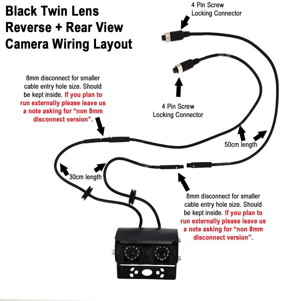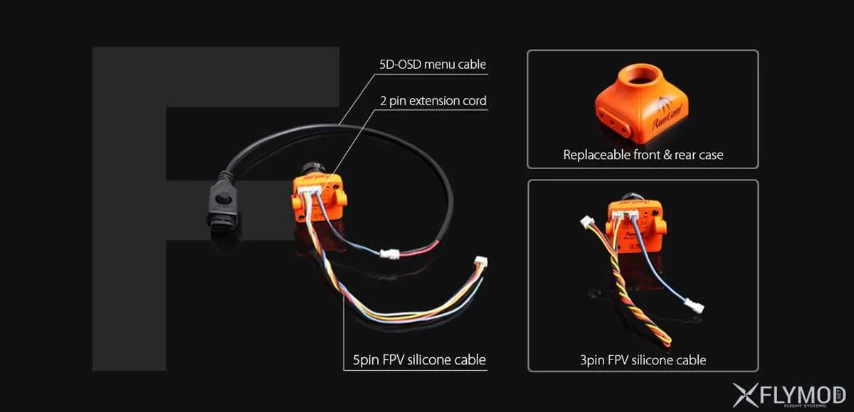
When working with imaging modules, ensuring proper pinout arrangement and electrical linkages is critical. For a flawless setup, refer directly to the specific connection sequence provided by the sensor’s technical documentation. Start by identifying the main power source terminals, which typically include VCC (positive voltage) and GND (ground), ensuring that they align with your circuit’s power supply ratings.
Key component connections like video output pins and clock signals need special attention. Verify each lead’s function, matching them with the corresponding signals from your processing unit or display interface. The most common issue arises from incorrect grounding or improper signal routing, leading to signal interference or failure to transmit data.
Use the provided voltage and current ratings to avoid overloading your device. Testing each connection for continuity and voltage stability before finalizing the build can save considerable time and effort. Also, consider the impact of cable length and shielded cables when routing high-frequency signals, as these factors can significantly affect performance.
Lastly, ensure that all components are adequately insulated to avoid accidental short circuits. It’s advisable to double-check the configuration before powering up to minimize risks. With careful attention to detail, you can achieve a reliable and high-quality setup that meets your system’s needs.
Essential Pinout Connections for Image Sensor Modules
For optimal performance, always ensure that the power lines, signal paths, and grounding are correctly configured to prevent signal degradation or malfunction. The power source should be connected to the VCC terminal, providing a stable 3.3V or 5V, depending on the sensor specifications. Grounding must be solid and directly connected to the GND terminal to avoid voltage spikes.
Signal outputs, such as video and sync signals, should be carefully routed to ensure minimal interference. For video output, ensure the data transmission follows the manufacturer’s recommended standards for pixel clock, horizontal, and vertical sync rates. The horizontal sync (HS) pin manages line-based timing, while vertical sync (VS) dictates frame-based timing, crucial for stable image display.
Important: The clock signal, often labeled as CLK or XCLK, should be properly matched to the sensor’s required frequency to avoid improper data capture. A mismatch can lead to corrupted image data or incomplete frames.
Additionally, use the right type of capacitors between power pins to filter noise effectively. A 100nF ceramic capacitor is typically recommended near the power input for stability. Pay close attention to the orientation of any polarized components, such as electrolytic capacitors, as incorrect installation can lead to system failure.
When connecting the sensor to a processing unit, ensure the interface pins (such as I2C, SPI, or parallel data) are wired securely, respecting their voltage levels to prevent communication errors. Always check the datasheet for pinout details specific to the module you are working with.
Lastly, ensure that all connections are firm and properly insulated. Loose connections, even with minimal resistance, can lead to noise or power instability that degrades the performance of the module.
Identifying Pinouts and Connections in Image Sensor Modules

When working with image sensor modules, it is crucial to accurately identify the pinouts for proper functionality. Typically, these components include multiple pins that manage power, video signal output, ground, and sometimes control signals. To begin, locate the power supply pins, usually labeled VCC or VDD, which connect to the positive voltage input (commonly 3.3V or 5V). The ground pin (GND) is typically next to the power pin, providing a reference for the electrical system.
The output pins, responsible for video signal transmission, are often divided into analog or digital signals. For analog video output, look for the Y (luminance) or CVBS (composite video) pins. In some models, these signals may be accompanied by synchronization pins such as VSYNC and HSYNC, which synchronize the scanning process.
Control pins may vary based on the specific model and can include options like RESET, SHUTTER, or FOCUS control. These pins allow the user to manipulate the functionality of the sensor, such as resetting the device or adjusting focus and exposure settings.
It’s important to cross-reference with the module’s datasheet to avoid misidentifying pins, as incorrect connections can damage the module or result in suboptimal performance. Pinouts can vary slightly depending on the manufacturer, even within similar sensor types, so double-check the labels and pin functions before proceeding with any wiring.
Understanding Signal Flow in Imaging Sensor Circuit Connections
To effectively interpret and troubleshoot the circuitry of imaging sensors, it’s crucial to grasp the flow of signals through the components. Here are key aspects to focus on:
- Signal Capture: Light hits the sensor elements, generating electrical signals that are then converted to analog form. This process starts at the photodiodes.
- Amplification: The weak analog signals need to be amplified to become strong enough for further processing. This step is crucial for clear image output.
- Analog to Digital Conversion (ADC): After amplification, signals are converted into digital form by an ADC unit for easier handling by the processing system.
- Signal Routing: Proper routing is critical to direct signals to the relevant sections, including video processors, memory, and other modules. This requires precise connection mapping.
- Signal Processing: Once digital data is routed, it is processed through algorithms that adjust contrast, color, sharpness, and other image characteristics.
- Output: After processing, the final image data is sent to display or storage devices. This output could either be in the form of a live feed or stored as a static image file.
Each component in the sensor circuit plays a vital role in maintaining the integrity of the signal throughout the entire flow. Proper connection of each segment ensures reliable operation and high-quality image capture.
Common Troubleshooting Tips for Wiring Issues

Check for loose or disconnected cables first. Even a slight gap in the connection can cause intermittent or total signal loss. Ensure that all plugs are securely inserted into their corresponding ports, especially at the camera and monitor ends.
Inspect the connectors for corrosion. Any visible rust or build-up on pins can result in poor conductivity. Clean the contacts using a soft cloth or an alcohol-based cleaner, being careful not to damage the components.
Verify the power supply. Insufficient voltage can lead to dim or flickering images. Use a multimeter to check that the power source is providing the correct output as specified in the equipment’s manual.
Look for signal interference. Nearby electronic devices or power cables can introduce noise into the video feed. Moving cables away from high-voltage or electromagnetic sources often resolves these issues.
Test with a known-good cable. A faulty cable is a common issue and can be difficult to diagnose. Replacing it with a new, verified cable can rule out the possibility of a damaged conductor.
Ensure proper grounding. Grounding issues often result in image distortion or instability. Check the grounding point and ensure it’s properly connected to avoid voltage fluctuations.
Review the installation environment. Excessive humidity, extreme temperatures, or exposure to direct sunlight can degrade cable insulation and connectors. Keep wiring and connections in a controlled, protected environment to prolong their lifespan.
If the system still fails, check for firmware or software conflicts. Occasionally, improper settings or outdated software can cause poor communication between components, requiring an update or reset.