Understanding the routing system is crucial for maintaining the efficiency of your water filtration unit. The rerouting mechanism allows for system adjustments, ensuring proper water flow and minimal downtime for maintenance or repairs. This element is typically used to control the passage of water through the filtration process, enabling the user to manage water flow without affecting the filtration itself.
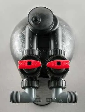
The mechanism’s design features a simple yet effective structure, consisting of a set of connectors and control knobs that regulate water direction. By adjusting this component, one can easily prevent water from passing through the filtration unit when needed, while still ensuring that the rest of the system operates as intended.
Installation considerations include ensuring that the system is correctly integrated with both the inlet and outlet pipes. Proper alignment of all parts will help avoid potential leaks and ensure a smooth flow of water when the rerouting feature is engaged. Make sure to check for any wear or damage to the connectors over time to keep the system functioning optimally.
Understanding the Flow Control Mechanism

Ensure that the system’s flow management is properly configured before installation to avoid bypassing filtration. Adjust the flow path so that untreated water does not interfere with the filtration process during maintenance or repair. Always confirm the correct placement of the diverter to prevent any cross-flow between the untreated and filtered streams. Regular inspection of the flow control component will help avoid clogging or malfunctions. If necessary, replace seals or gaskets to maintain an effective seal between the treated and untreated water channels.
When setting up or troubleshooting, verify that the diverter is properly aligned with the main filtration unit. This will ensure the untreated water remains isolated from the treated output. Misalignment can result in inefficient filtration or pressure build-up, potentially damaging the system. If a component is not functioning smoothly, perform a quick check for blockages or wear, and consult the system manual for specific flow path adjustments.
Understanding the Function of the Bypass Mechanism in Filtration Systems
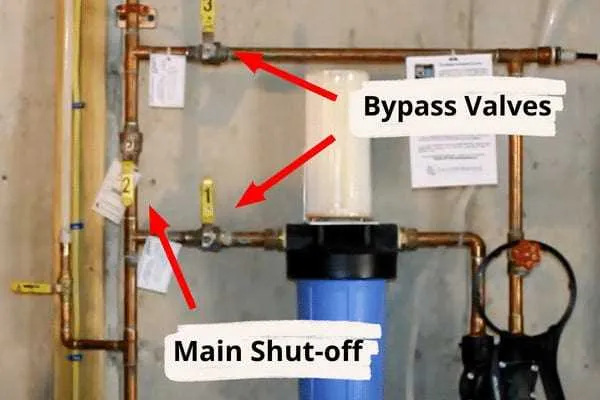
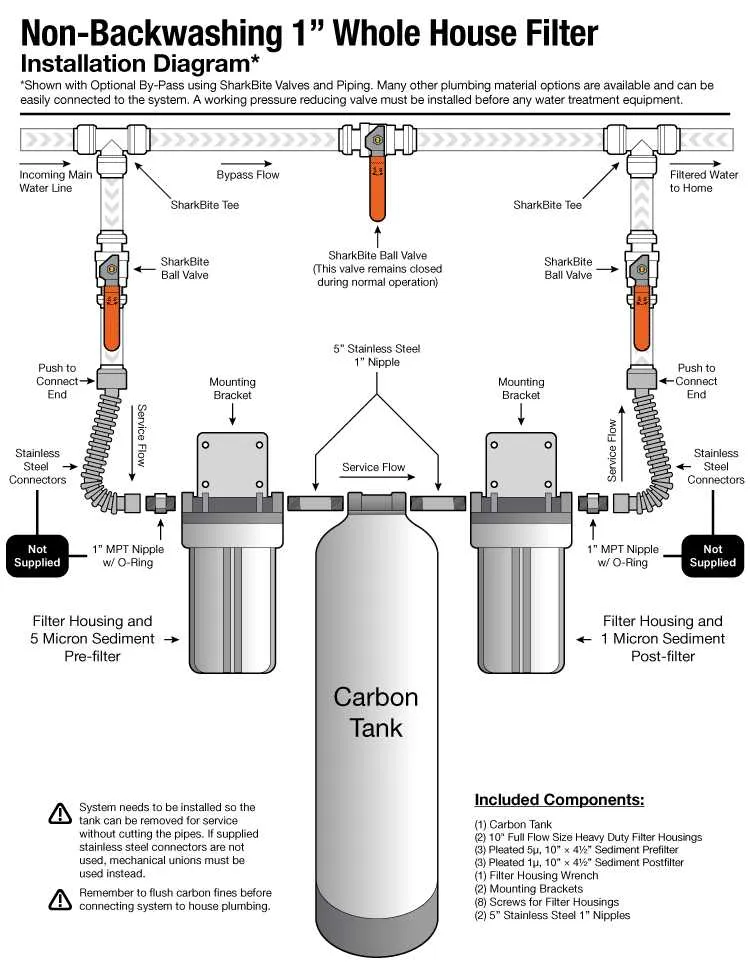
When performing maintenance or when regeneration is required, it is essential to know how to divert water flow away from the filtration process without disrupting the entire system. The diversion system allows for this by directing the flow through an alternate path, bypassing the main filtration components temporarily. This ensures that you still have access to water while preventing damage or unnecessary wear to the filtering parts.
Key Considerations: Always ensure that the system is properly configured to allow for easy redirection of flow. In cases where the filtration medium needs to be replenished, or if there is an issue with the filtration process, activating the redirection feature can maintain water supply without interruption. It also helps prevent overuse or excessive strain on the filtering components during maintenance.
Tip: Regular checks of the diverter mechanism ensure that it operates smoothly and does not cause water pressure issues. Keep an eye on the condition of the system’s seals and connections to avoid leaks when the flow is rerouted.
How to Identify Components in a Water Softener Bypass Valve Diagram
Begin by recognizing the inlet and outlet ports, as they are crucial for the flow direction of the treated and untreated fluids. Typically, the inlet port is positioned at the top or side of the system, while the outlet port leads the flow out of the unit. These are usually labeled with arrows indicating the flow direction.
Look for the control knobs or levers, which are used to adjust the flow path. These components are often represented as circular or rectangular elements, and their function is to switch between treatment and bypass modes.
Next, identify any check valves, which are designed to prevent reverse flow. These are often depicted with a one-way arrow inside a cylindrical shape. They are essential for maintaining system efficiency and preventing contamination.
Find the seal or gasket placements, which are typically shown surrounding moving parts. These seals prevent leakage and maintain pressure within the system. They are often highlighted to ensure proper installation.
Lastly, examine the flow control elements, such as small openings or flow restrictors, that regulate the amount of fluid passing through the system at a given time. These are usually small, circular components placed along the flow path.
Step-by-Step Guide to Installing a Diverting Mechanism in Your Filtration System

Start by ensuring all components are turned off and the system is properly drained. You don’t want any residual pressure when working with the components.
- Step 1: Disconnect the system from the water supply lines to avoid accidental leakage.
- Step 2: Remove the existing assembly where the diversion is to be installed. This may require unscrewing or unclipping certain connections depending on your unit’s design.
- Step 3: Identify the correct location on the assembly for the new unit. Typically, this will be near the inlet and outlet ports of the filtration unit.
- Step 4: Place the new part carefully into the designated area. Ensure it fits snugly, and check for any misalignment that could cause future malfunctions.
Once everything is in place, tighten any connections, making sure that no part is too loose, which could lead to leaks over time. Double-check the assembly for any visible gaps or weaknesses in the seals.
- Step 5: Reconnect the system to the water supply and check for leaks by slowly turning on the flow. Make sure the mechanism is functioning properly.
- Step 6: Test the system’s efficiency to ensure that the new part is correctly rerouting the flow as intended.
After installation, you should periodically inspect the setup to ensure it remains intact and functions as expected.