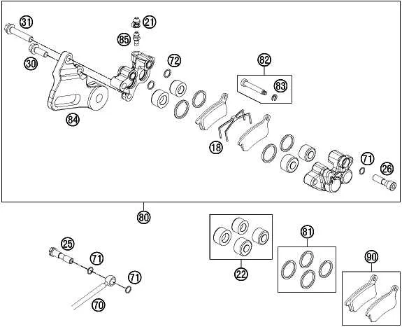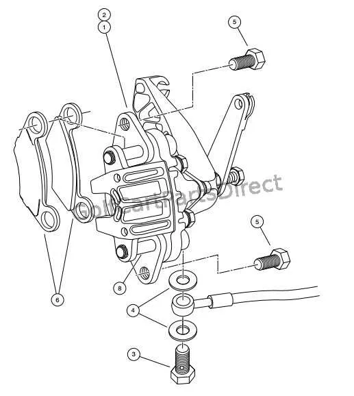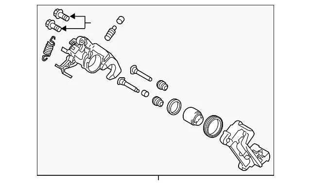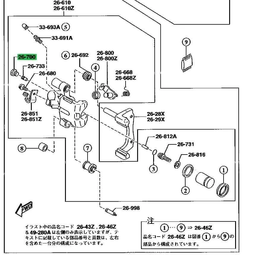
Start by identifying the piston housing orientation. This component typically aligns with the rotor’s inner surface and must move freely within its bore. Binding or corrosion at this point leads to uneven wear. Inspect the seal groove for debris and ensure the dust boot sits flush to prevent moisture ingress.
Next, examine the slide pin configuration. These guide elements are crucial for proper movement under load. Each pin must be adequately lubricated with high-temperature grease and inserted into the mounting bracket without resistance. Use a torque wrench to secure the pins as per factory specifications, typically ranging between 20–30 Nm.
Check the alignment of the mounting bracket in relation to the rotor and hub. The bracket should sit square with no lateral movement. Misalignment often results from worn bushings or improper installation of spacers. Replace worn shims and retorque fasteners to manufacturer-prescribed values.
Monitor the condition of the actuation mechanism, especially if equipped with an integrated hand-lever interface. The screw-in piston must rotate smoothly and retract completely when disengaged. Any signs of resistance indicate internal corrosion or mechanical damage requiring disassembly and cleaning.
Rear Brake Caliper Diagram

Ensure the actuator arm is aligned precisely with the parking lever’s pivot to prevent binding during cable tension. Use a torque setting of 28 Nm when fastening the carrier bolts to avoid thread stripping while maintaining structural integrity.
Inspect the piston seal lip for uniform compression against the housing; asymmetrical seating may lead to fluid leaks. The dust boot must be clipped fully into its groove to protect the sliding mechanism from grit intrusion.
Lubricate guide pins with high-temperature synthetic grease, avoiding petroleum-based compounds that degrade rubber sleeves. Check the retraction spring for tension above 8 N; a weaker return may result in drag and overheating.
Measure the distance between pad abutment ends and the mounting bracket–target a clearance of 0.3 mm to minimize rattle while allowing free movement. Replace any hardware showing signs of corrosion or galling to preserve consistent performance.
Identifying Key Components and Their Placement

Begin by locating the piston housing, typically positioned at the center of the assembly. This cylindrical unit compresses the friction material against the rotating disc when pressure is applied. Ensure it moves smoothly within its bore to maintain optimal response.
Next, inspect the mounting bracket, found affixed to the suspension knuckle. This structure secures the entire mechanism and guides pad movement. Check for secure bolt connections and clean sliding surfaces to prevent uneven wear.
The guide pins are inserted through the bracket, aligning the movable section with the fixed frame. Lubricate them with high-temperature grease to avoid sticking or noise during operation.
Examine the pad retainers–spring clips or plates located at the top and bottom edges. These components hold the friction blocks in place and reduce vibration. Replace if signs of corrosion or deformation are present.
Finally, identify the adjuster mechanism, usually integrated into the piston or mounted externally. This unit compensates for lining wear. Confirm its function by checking for automatic travel reset after actuation.
Understanding Hydraulic Flow and Piston Movement
Begin inspection by verifying that the master cylinder maintains consistent pressure across the lines. Any air pockets or inconsistent fluid delivery will prevent full piston engagement.
- Use a transparent hose to observe fluid return during pedal release; sluggish movement indicates internal blockage or degraded seals.
- Measure piston retraction with a dial gauge–typical movement should not exceed 1-2 mm after release. Larger displacement suggests faulty dust boots or excessive seal flex.
- Ensure the bore surface is free of corrosion; even minor pitting can disrupt uniform hydraulic expansion.
During actuation, fluid enters the chamber via the banjo bolt or direct line fitting. Check that inlet ports are clean and unobstructed. Residue accumulation here limits pressure build-up and delays pad contact.
- Flush the system with DOT-specified liquid at intervals no longer than two years to maintain optimal flow characteristics.
- Inspect piston seals for uniform compression during manual pressing. Deformation or asymmetry indicates uneven force distribution.
- Replace any components where piston sides show scuffing, a clear sign of off-axis motion during cycling.
Always test assembly on a bench rig with controlled pressure input. Observe piston movement through the full travel range–smooth, linear motion confirms system integrity.
Analyzing Common Wear Points and Maintenance Zones

Prioritize inspection of the piston seals and sliding pins, as these components most frequently suffer from corrosion and debris buildup, leading to uneven pad wear and decreased responsiveness. Ensure the dust boots remain intact to prevent contamination that accelerates degradation.
Check the mounting brackets and guide pins for signs of binding or excessive play, which can cause misalignment and uneven friction surface wear. Lubricate these areas with high-temperature grease to maintain smooth movement and prevent premature failure.
Examine the contact points between the friction pads and the carrier assembly. Excessive scoring or glazing on these surfaces reduces braking efficiency and requires resurfacing or replacement. Monitor pad thickness regularly, replacing them once wear exceeds manufacturer-specified limits, typically around 3mm.
Inspect the hydraulic piston for leaks or surface pitting that can impair fluid pressure and cause uneven clamping force. Replace any compromised seals immediately to maintain system integrity and safety.