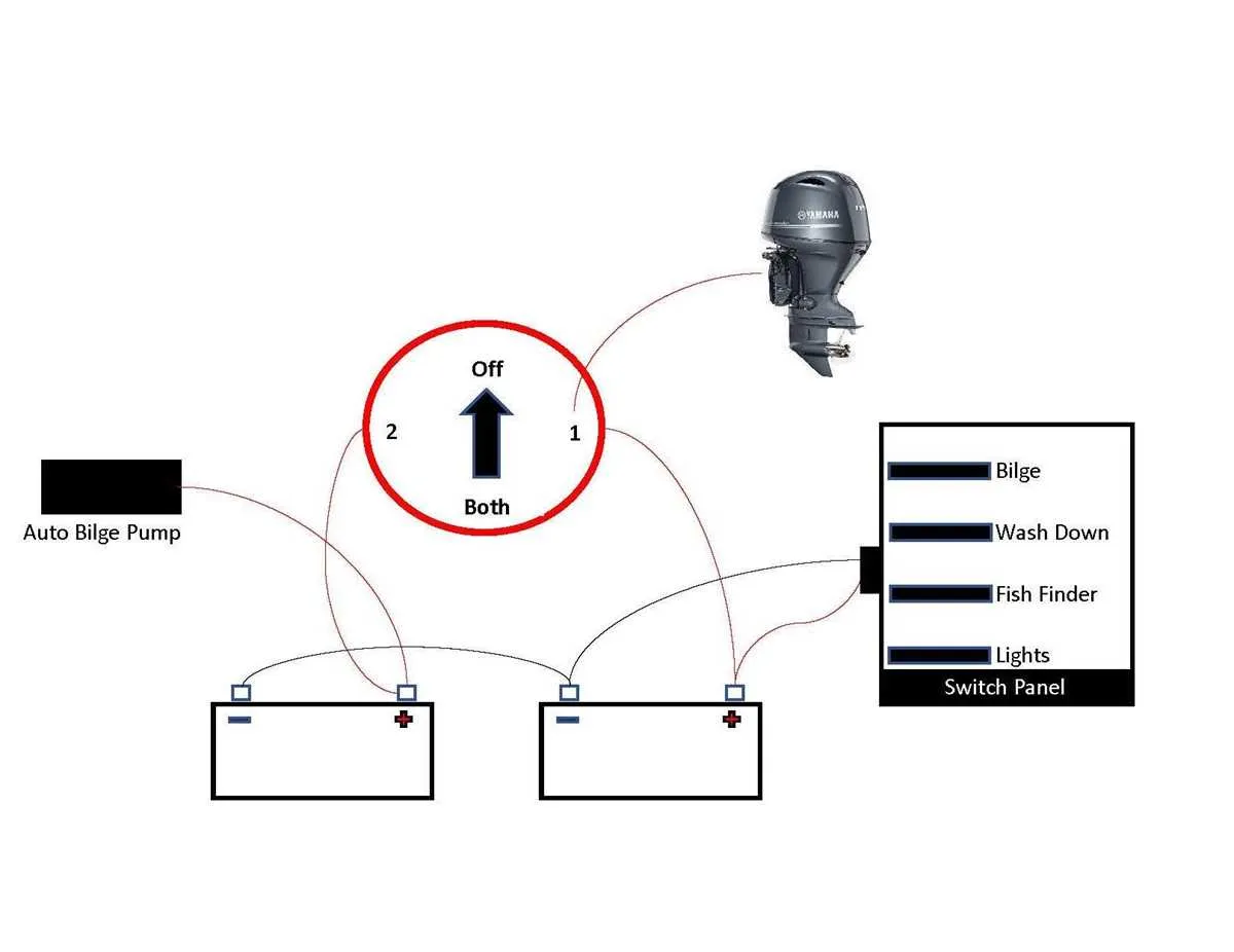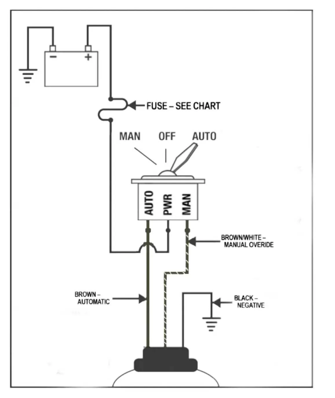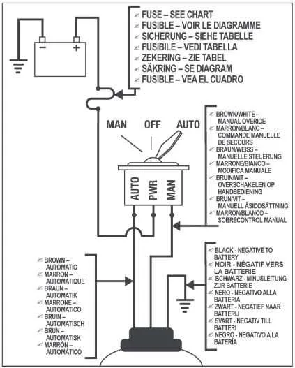
For a reliable water evacuation system, proper connections and power routing are crucial. Begin by selecting the right gauge wire based on the current draw of your system. A 12 AWG wire is typically suitable for units pulling around 10-15 amps. Ensure the wire length does not exceed recommended limits to avoid voltage drops that may reduce performance.
Use a marine-grade fuse to protect the circuit. A 15-amp fuse is commonly recommended, but always verify with the system’s specifications. The fuse should be placed as close to the power source as possible to prevent damage to the wiring and components in case of short circuits.
When connecting the sensor switch to the power line, make sure the sensor is positioned in the correct spot to detect rising water levels. This switch should be wired to activate the pump at the specified water height. Double-check that the switch is properly sealed and protected against corrosion to ensure consistent functionality over time.
For the power source, it’s best to connect the system directly to a dedicated circuit breaker on the boat’s panel. This ensures that the pump has sufficient power, and also provides a quick disconnect in case of system failure. Always test the entire setup before use, checking for proper operation of the sensor and pump when the water level is raised artificially.
Installation Guide for an Automatic Water Removal System

To install a reliable water removal system on your boat, follow these steps to wire the components correctly:
- Connect the float switch to the power source. The float switch should be positioned at the lowest point of the hull where water accumulates.
- Wire the power source to a fuse. Ensure the fuse rating matches the system’s requirements to prevent electrical overload.
- Route the positive wire from the power source to the float switch. From there, connect it to the motor’s power input.
- Install the ground wire to complete the circuit. Make sure it is securely fastened to the boat’s grounding point.
- Test the system by simulating water rise to ensure proper activation of the motor and float switch.
Ensure that all connections are waterproof, especially around the battery and power terminals, to prevent corrosion. Additionally, check the system regularly for proper function to avoid unexpected failures during use.
Understanding the Power Supply Requirements for Rule Bilge Pumps

Ensure proper voltage compatibility before installation. Most marine devices operate on either 12V or 24V DC systems. Verify that your power source matches the pump’s voltage specifications to avoid damage and ensure efficient operation.
Determine the necessary current rating to prevent overloading your electrical circuit. Check the amp rating of the device to ensure that the wiring and fuse protection are appropriately rated. For instance, a 3.5A rated device should be connected to wiring that can handle higher currents to minimize risk of overheating.
Use correctly sized wiring for safe and reliable operation. Select cables with sufficient gauge to minimize voltage drop, especially for longer runs. A general guideline is to use 14 AWG wire for short distances and 12 AWG for longer distances. Verify that the wiring is marine-grade, designed to withstand exposure to moisture and saltwater.
Install fuse or circuit breaker protection to safeguard the system against potential short circuits or overloads. A fuse rated slightly above the maximum current draw will help prevent catastrophic failures while ensuring the device operates safely under normal conditions.
Consider power source location when routing cables. Position the battery or power supply close to the pump’s intended installation point to reduce the risk of voltage loss. Also, ensure all connections are corrosion-resistant and properly sealed to maintain performance under harsh marine conditions.
Step-by-Step Guide to Connecting a Rule Bilge Pump to a Float Switch
Ensure both the water removal device and the float switch are ready for installation. Choose a location for the float switch that allows it to rise and fall freely with the water level.
1. Prepare the Float Switch: Mount the float switch securely in the desired position, ensuring it is unobstructed by any nearby components. The switch should be installed in a place where it can detect water levels accurately.
2. Connect the Power Supply: Use a fused power line that connects the switch to the battery. Ensure the fuse rating matches the requirements of the float switch and the water removal device.
3. Wire the Switch to the Water Removal Device: Connect the output terminal of the float switch to the control terminal of the water removal device. This wiring allows the float switch to activate or deactivate the device when the water reaches a certain level.
4. Ground the System: Attach the ground wire from both the device and the switch to a suitable ground point, ensuring a solid connection to prevent any electrical malfunctions.
5. Test the System: After completing the connections, test the float switch by manually raising and lowering the float. Check that the device turns on when the float is raised and turns off when it is lowered.
6. Secure the Wires: Use cable ties or clips to secure the wiring and prevent any movement that could lead to wear or disconnections over time.
Once the installation is complete and tested, ensure the connections are tight and waterproof, as exposure to water could cause short circuits or failure.
Common Mistakes to Avoid When Installing Marine Water Removal Systems
Ensure all connections are secure and properly insulated. Loose or exposed terminals increase the risk of electrical short circuits, leading to potential system failure. Use marine-grade connectors that are designed for wet environments to prevent corrosion.
Avoid undersizing the cables. Select wiring that matches the amperage rating of your system. Too small a gauge can cause overheating, potentially damaging components and reducing system efficiency. Always check the manufacturer’s recommendations for the correct cable size.
Do not skip over proper grounding. An ungrounded system can lead to erratic behavior and even failure of the motor. A solid, clean ground connection is critical for stable operation and longevity of the device.
Incorrectly routing cables is a frequent issue. Avoid running wires near heat sources or moving parts, as this can result in wear and tear. Proper cable management with appropriate clamps prevents rubbing and accidental cuts to insulation, which could lead to failures.
Double-check the power source capacity. Using a circuit that cannot support the required load will lead to overheating and may trip breakers or damage fuses. Always install a fuse or circuit breaker in line with the electrical system to protect the components from power surges.
Finally, ensure the control switch is wired to an easily accessible and dry location. Avoid placing switches where water exposure is likely, as moisture can compromise their functionality and create safety hazards.