For anyone maintaining or repairing automatic flush systems, it’s crucial to identify each individual component to ensure proper functioning. This can prevent unnecessary malfunctions and improve the longevity of the entire system. Start by reviewing the control mechanisms–these are the core elements that regulate water flow and manage the flushing process.
Next, focus on the seal and diaphragm assemblies. These play a pivotal role in ensuring that water pressure is maintained and that there are no leaks. Faulty seals or diaphragms can result in water wastage and inefficient performance.
It’s also important to inspect the sensor and activation components. These detect when a user is present and trigger the flushing action. If the sensor is out of alignment or compromised, the system may fail to function properly. Regular calibration and testing of these parts are essential to maintaining accurate activation.
Lastly, examine the flush valve mechanism thoroughly. This device controls the release of water from the tank into the bowl. Over time, mineral build-up or wear and tear can impair its efficiency, leading to inconsistent flushing. A regular check-up can prevent costly repairs and ensure reliable operation.
Understanding the Components Layout
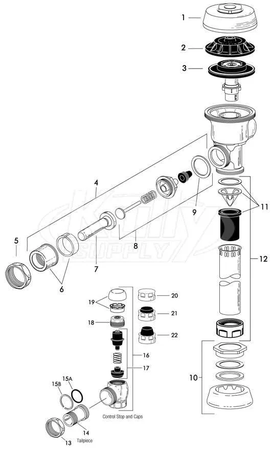
Ensure you have the correct identification for each component before starting assembly. The key to smooth operation lies in recognizing the specific parts of the flushing mechanism and their arrangement. Focus on isolating the control mechanism, ensuring the seal is intact, and checking for any misalignments in the flow control elements. Refer to the technical drawing for a detailed view of part placements, especially the water flow regulator and actuator components.
Verify that the inlet and outlet ports are free of any obstructions. The seal should be examined for wear or damage to prevent leaks. The actuator is crucial for proper operation, so check its connection to the main assembly, ensuring the linkage is functioning properly. Use the diagram to confirm the correct orientation and fitting of each element. Pay particular attention to the location of the overflow valve and its connection to the reservoir for proper pressure balance.
Before reassembling, inspect each gasket and ensure they are placed in their specific slots. This ensures no bypassing of water or air. If replacing any of the components, compare the new parts with the diagram to avoid incorrect installation. Each piece must fit securely to maintain the integrity of the system.
In case of malfunction, refer back to the illustration to troubleshoot specific parts like the pressure regulator or flush mechanism, which can often be sources of failure. Make sure all fittings are tightened according to the manufacturer’s guidelines and check the entire system for leaks before use.
Identifying Key Components in Sloan Valves

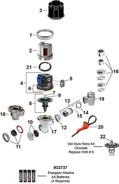
To properly service and maintain these fixtures, it’s essential to recognize each functional element. Start by identifying the main actuator, which controls water flow based on motion detection or manual operation. Check the sensor module or switch to ensure accurate response to user input.
Next, locate the diaphragm, a crucial piece that regulates pressure within the system. Pay attention to the solenoid, which controls electrical signals to open or close the flow of water when needed. The manual override button is another vital feature, ensuring functionality even in the absence of automatic sensors.
Inspect the flush valve mechanism, as it determines the efficiency of water use. This component works in conjunction with the timing system to ensure proper flushing intervals. Always check the mounting hardware, as any misalignment can affect overall performance.
Lastly, verify the filter or strainer, which prevents debris from disrupting flow. Ensuring that all these components are in good working order can significantly extend the life of the system.
Step-by-Step Assembly of Sloan Valve Parts
Begin by verifying the compatibility of internal components based on model specifications. Ensure all seals and connectors are clean and undamaged before installation.
- Insert the diaphragm assembly into the upper chamber, aligning the flow-control orifice with the designated outlet slot.
- Position the refill head over the diaphragm, ensuring the guide pin seats into the corresponding channel without rotation.
- Secure the compression spring on top of the refill head; verify vertical alignment to maintain consistent recoil force.
- Attach the actuator cap by threading it clockwise; use a torque wrench calibrated to manufacturer tolerances to prevent over-tightening.
- Install the vacuum breaker tube, pressing it firmly into the outlet spud. Confirm airtight fit by applying soapy water and checking for bubbles.
- Reconnect the control stop. Turn the screw counter-clockwise to restore water flow and test for leaks under full pressure.
Use only factory-approved lubricants on rubber surfaces. Replace all gaskets during reassembly to ensure optimal performance and compliance with maintenance standards.
Common Troubleshooting for Sloan Valve Parts
Constant water flow: Replace the diaphragm assembly if water doesn’t stop after flushing. Inspect the relief valve for debris; clean or swap it if damaged.
Weak or incomplete flush: Check if the flow control is clogged. Remove mineral deposits using vinegar or a commercial descaler. Confirm the correct flush volume regulator is installed for the fixture type.
Handle sticks or is difficult to press: Lubricate the handle packing or replace it if worn. Ensure the handle gasket is properly seated and not distorted.
Noise during operation: Examine the bypass orifice for blockage; clear it with a thin wire. Secure mounting connections to reduce vibration.
Flush initiates without user input: Inspect the sensor module for moisture or electrical faults. Replace batteries and recalibrate sensor range.
Leaks at the coupling area: Tighten the spud coupling nut and ensure the gasket is not deteriorated. Replace with a new seal if necessary.