Shear and bending moment diagrams are analytical tools used in conjunction with structural Cheng, Fa-Hwa. “Shear Forces and Bending Moments in Beams” Statics and Strength of Materials. New York: Glencoe, McGraw-Hill, .
Print. Statics of Bending: Shear and Bending Moment Diagrams. David Roylance.

Department of Materials Science and Engineering. Massachusetts.
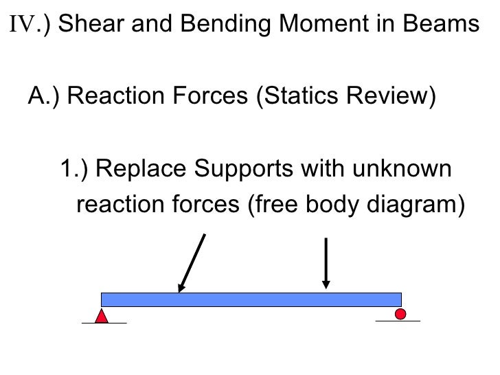
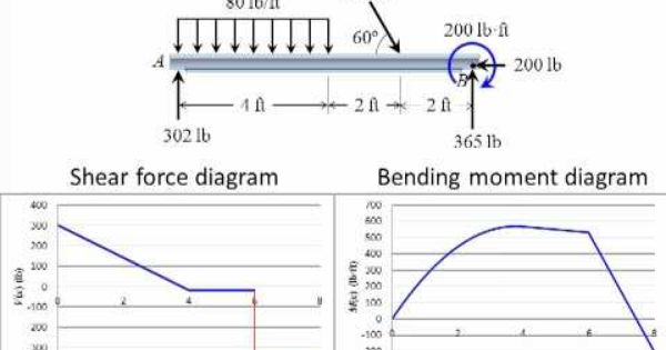
Shear and moment diagrams are a statics tool that engineers create to determine the internal shear force and moments at all locations within an object. Start by. If the shear force and bending moment are calculated and graphed, then the maximum and minimum of each are easily identified and located.
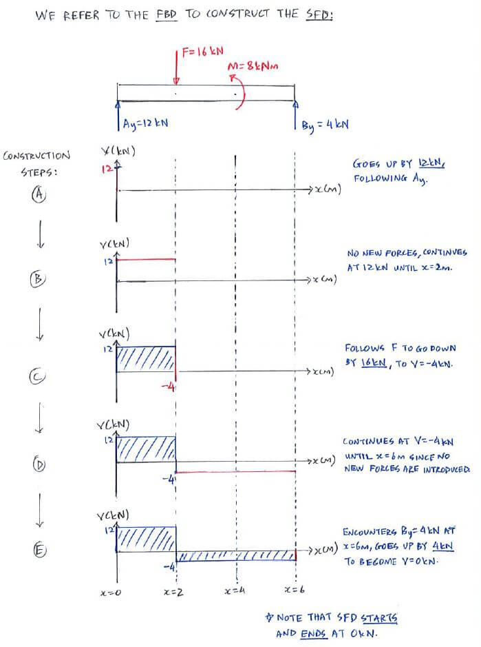
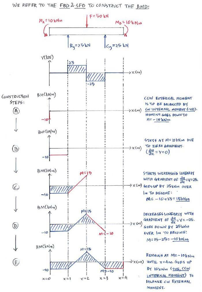
are called the shear diagram and the moment diagram. ➢ Developing the shear and moment functions for complex beams can be quite tedious.
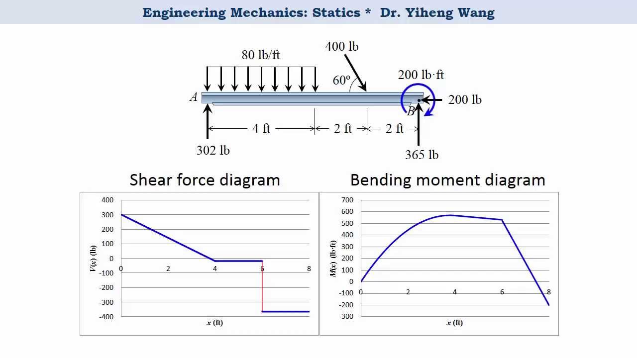
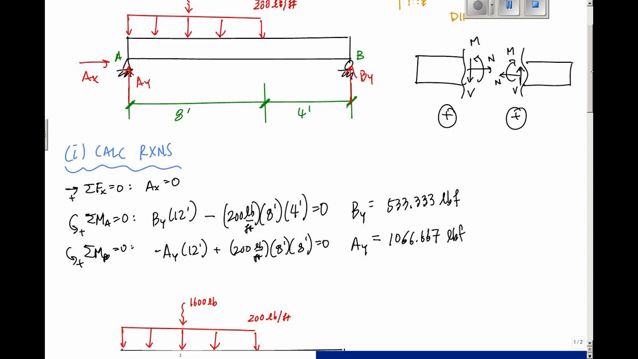
Shear and.C Shear Force and Bending Moment Diagrams. You probably can tell from the examples previously that the shear force SF and bending moment BM varies along the beam, due to the varying loads.
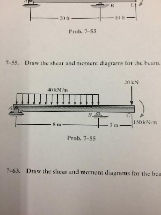
*By the way, SF and BM diagram is probably the most important topic in this entire Statics course. If the shear equations (Eqs.
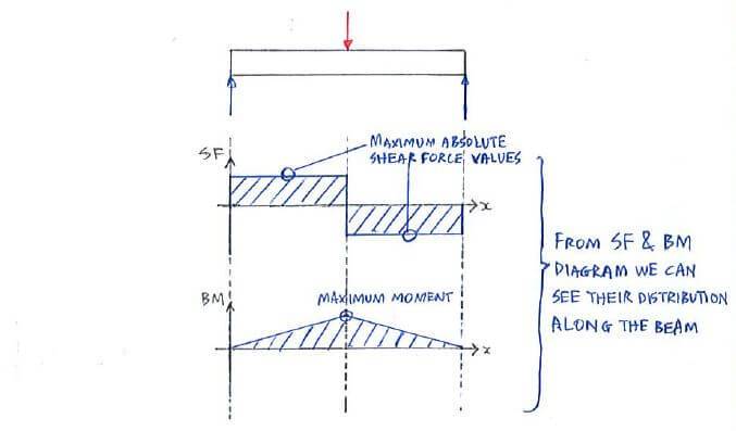
1 and 3) are graphed on one single axis and the moment equations (Eqs. 2 and 4) on another single axis, the shear and moment diagrams are obtained as shown on the left. The location for maximum and minimum shear force and bending moment are easily found and evaluated.
Statics of Bending: Shear and Bending Moment Diagrams David Roylance Department of Materials Science and Engineering Massachusetts Institute of Technology. Shear and moment diagrams are a statics tool that engineers create to determine the internal shear force and moments at all locations within an object.
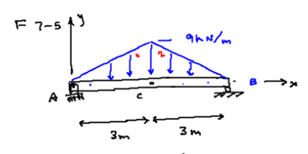
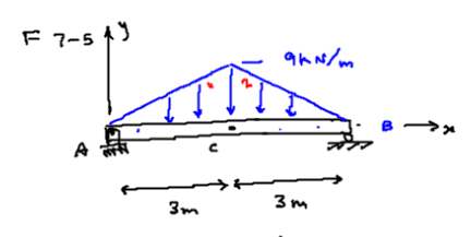
Start by locating the . Shear and Moment Diagrams Now that the shear and moment is known for each section of the beam, the results can be plotted. The resulting graphics are called the shear diagram and moment diagram.Theory | C Shear Force and Bending Moment Diagrams | StaticsShear and moment diagram – Wikipedia
