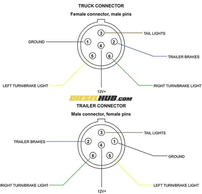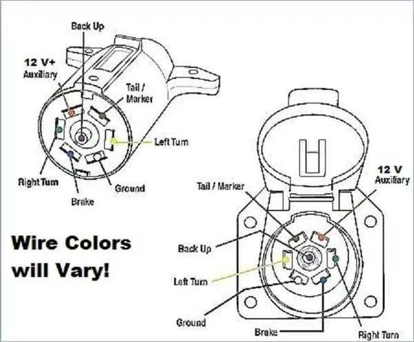
For reliable electrical operation of your vehicle’s attached unit, it’s essential to correctly configure the connector system. Ensuring each contact is properly wired guarantees the functionality of various systems, such as indicators, brakes, and power supply. A standard connector with seven terminals serves as the most common solution in modern vehicles, providing the necessary circuits for diverse electrical functions.
Start by identifying each terminal’s purpose. The first terminal handles the ground connection, which is critical for the entire system’s safety and stability. The second provides power for the indicators, while the third handles the rear fog lights. Other terminals are designated for brake lights, reverse signals, and additional functions like charging the battery or supporting auxiliary systems.
Ensure accurate color coding of wires to avoid misconnection. Each function must be matched with the corresponding wire color to prevent malfunction or damage to electrical components. The standard color scheme helps simplify the process and minimize errors, but always verify with the manufacturer’s specifications when in doubt.
Proper installation not only ensures optimal performance but also reduces risks associated with electrical failures. Double-check each connection after installation and regularly inspect for wear or corrosion, especially in areas exposed to moisture. This will extend the lifespan of your system and maintain its efficiency.
7-Contact Connector Pinout for Towing Systems
To ensure proper function of your towing system, it’s essential to wire each connection accurately. The 7-pin connector typically handles connections for the brake lights, indicators, reverse lights, and ground, among others. The arrangement of pins ensures a reliable and safe electrical flow between the towing vehicle and the attached unit.
For optimal performance, assign the following roles to each pin starting from the top view of the connector: Pin 1 – Left Turn Signal; Pin 2 – Ground; Pin 3 – Right Turn Signal; Pin 4 – Brake Lights; Pin 5 – Reverse Lights; Pin 6 – Tail Lights; Pin 7 – Electric Brakes. This configuration supports standard functionalities for both vehicle and trailer systems.
Pay close attention to the pin orientation when connecting. Ensure that you’re inserting the right wire into the correct socket to prevent faults and potential hazards. Always use high-quality, durable wires for the connections to avoid overheating and premature wear.
Understanding the 7 Pin Connector Color Code

The 7-pin connector uses a standard color code to ensure proper function across different vehicles and equipment. Each wire color corresponds to a specific electrical function. Here’s the breakdown:
White: Ground connection, providing a common return path for the electrical circuit.
Brown: Powers the rear and side running lights, illuminating the rear section of the vehicle.
Green: Controls the right-turn signal and brake lights, providing the necessary indicators for right-hand turns.
Yellow: Manages the left-turn signal and brake lights, indicating left-hand turns.
Blue: Used for electric brakes, activating the braking system in the connected equipment.
Black: Provides power to auxiliary circuits, such as the interior lighting or battery charging of the connected unit.
Red: Activates reverse lights, ensuring visibility when the vehicle is in reverse motion.
Correct wiring and matching colors between the towing and towed units are essential for safe and functional connection. Double-check that each wire matches the color coding before making any electrical connections.
How to Properly Connect a 7-Prong Plug for Your Vehicle
Start by ensuring that the vehicle’s electrical system is turned off before beginning any work. Then, identify the correct wiring colors for the connection: typically, brown for the right-side indicators, yellow for the left-side indicators, and green for the brake lights. The white wire should be for the ground connection, while the blue wire is used for the reverse lights. The red wire is generally for the brake controller, and the black wire provides power to accessories.
Secure the connection of each wire by stripping back the insulation about half an inch. Insert the exposed end of the wire into the corresponding terminal on the connector. Use a crimp tool to ensure a tight, secure connection. Make sure each prong is firmly in place, ensuring no loose ends or exposed wires that could cause a short circuit.
Once all connections are made, double-check that the wiring matches the vehicle’s socket configuration. Test each function with the system powered on, verifying that the signal, brakes, and reverse lights are all functioning as expected. If any issues arise, recheck the connections to ensure they are correctly aligned and firmly in place.
Tip: Use a high-quality waterproof connector and apply dielectric grease to prevent corrosion and ensure longevity. Regularly check the connections for wear and tear to avoid future problems.
Common Connector Issues and Troubleshooting Tips
To ensure optimal performance, it’s essential to address common faults in electrical connections. Here are the most frequent issues and their solutions:
- Corroded Contacts: Over time, moisture can cause oxidation on contact points. Clean them with electrical contact cleaner and apply dielectric grease to prevent further corrosion.
- Loose Connections: Check for any loose or damaged terminals that may result in intermittent function. Tighten or replace connectors as needed.
- Faulty Grounding: A poor ground connection often leads to erratic operation. Ensure that the ground wire is securely connected to a clean, unpainted metal surface.
- Incorrectly Wired System: Verify the configuration matches the correct pattern for your setup. Recheck each wire’s position and function using a multimeter to avoid shorts or miswiring.
- Blown Fuses: If all connections appear intact but the system still doesn’t function, inspect the fuses. Replace any that are blown with the correct amperage rating.
- Damage from Overloading: Excessive current can damage the wiring or connectors. Ensure that the system isn’t drawing more power than the components are rated to handle.
Regular inspection and maintenance can prevent these issues from disrupting functionality. Use high-quality materials to ensure long-term reliability.