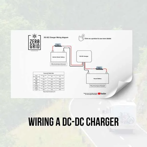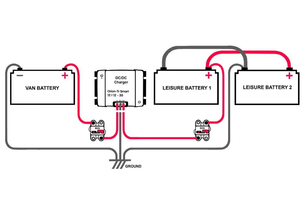
Ensure that the correct polarity is observed when setting up your DC power system. Connect the positive terminal of the power source to the positive side of your device, and the negative terminal to the negative side. This step is crucial to avoid damaging the system.
Use appropriately rated conductors to handle the current that will flow through the system. Underestimating the required gauge can lead to overheating, inefficiency, and even fires. Always refer to the power specifications of both the power source and the connected equipment to choose the correct wire thickness.
Incorporate safety fuses into the setup, placed near the power source, to protect both the source and the equipment from potential short circuits or overloads. Ensure that the fuse rating matches the maximum expected current for your specific application.
Wiring Setup for DC Power Supply
Ensure correct polarity when connecting the positive and negative terminals. Incorrect polarity can damage components or cause malfunction. Always use a voltmeter to double-check the voltage before proceeding with connections.
For effective current flow, choose cables with adequate thickness to handle the required amperage. Smaller wires will overheat, while too thick cables may be unnecessarily bulky and difficult to manage. A general guideline is to use 12 AWG wire for currents up to 20A and 10 AWG for up to 30A.
When connecting to a load, use a suitable fuse for overcurrent protection. The fuse rating should be 20% higher than the expected maximum current to prevent false triggers. Typically, a 30A fuse is ideal for setups expecting up to 25A of current.
Ground connections are critical for safety. Always connect the negative terminal of the power source to a ground point to prevent electrical hazards. A solid ground connection helps avoid potential electrical shorts.
Consider using a dedicated disconnect switch between the power supply and the load. This allows for easy maintenance and safety during any repair work. Ensure the switch can handle the maximum current of the system to avoid overloading.
Ensure all terminals are tightly secured to prevent any loose connections, which can lead to sparks or voltage drops, ultimately damaging equipment. Use terminal blocks or locking connectors for a reliable and safe connection.
Understanding DC Power Supply Pinout and Connections
When working with DC power systems, it is crucial to correctly identify the pinout and the connections associated with each terminal. The most common pins include positive, negative, and ground, which are essential for ensuring proper function and preventing damage to the equipment. Properly connecting the terminals based on their function is fundamental to achieving a safe and reliable setup.
Positive Pin: This pin is typically marked as +, and it is where the positive voltage is supplied to the device. Always ensure the correct polarity by double-checking before making any connections.
Negative Pin: Often marked as -, this is the return path for the current. It’s essential to securely connect this pin to ensure proper circuit functionality and minimize the risk of malfunction.
Ground Pin: Some setups may include a dedicated ground pin. This pin is used for safety purposes, providing a path for excess charge to dissipate safely, preventing electrical shock and equipment damage.
Additionally, make sure to use suitable wire gauge according to the current requirements. Underestimating the necessary thickness can result in overheating or potential fire hazards. It’s also advisable to check that all connections are tight and corrosion-free to ensure long-term stability.
Choosing the Right Wire Gauge for DC Power Setup
For a safe and efficient electrical connection, select the appropriate wire size based on the current rating and distance between components. The following guidelines help in determining the best gauge for optimal performance.
- Current Rating: Choose a wire that can handle the maximum current your system will draw. For example, a 10 AWG wire can carry up to 30 amps, whereas a 12 AWG wire is suitable for up to 20 amps.
- Distance Consideration: Longer wire runs result in voltage drop. For distances over 25 feet, consider increasing the wire gauge to compensate for the loss of power.
- Ambient Temperature: If the environment is hotter than standard conditions, opt for a thicker wire to prevent overheating.
For typical DC systems, the following wire gauges are commonly used:
- 18 AWG: Suitable for low power applications under 10 amps.
- 14 AWG: Ideal for moderate power systems around 15 amps.
- 10 AWG: Recommended for high-power setups up to 30 amps.
Ensure to factor in both the load and distance when deciding the gauge. Too small a wire can lead to excessive heating, while too large can be unnecessarily expensive and harder to work with.
Common Electrical Issues and Troubleshooting Tips

Check for loose connections: Ensure that all terminals are tightly connected. Loose connections can cause intermittent power flow or complete failure, leading to malfunction. Tighten screws and ensure that the contact points are clean and free from corrosion.
Inspect for incorrect polarity: Reversing the positive and negative terminals is a common mistake. This can result in malfunction or even damage to the system. Double-check the orientation of each wire before making connections.
Examine for short circuits: A short circuit between conductors can cause the system to fail or trip safety mechanisms. Test with a multimeter to detect continuity between wires that should not be connected.
Assess voltage stability: Insufficient or fluctuating voltage can impact performance. Measure voltage levels at key points and ensure they match the required specifications for smooth operation. Use a regulated power supply for consistency.
Replace damaged components: Over time, components like fuses or resistors can wear out or burn out. If these parts are faulty, replace them immediately to restore functionality and prevent further damage.
Verify grounding: Improper grounding can lead to poor performance or even safety hazards. Make sure the ground wire is securely connected and properly routed to a stable grounding point.
Inspect for overheating: Overheating of wires or connectors is a sign of excessive resistance or current draw. Check for discolored or melted components and address the root cause, such as undersized wiring or excessive load.
Test with an external load: If the system is not functioning properly, test it by connecting an external load. This helps confirm whether the issue is with the power supply or the connected device.
Use quality components: Always use high-quality cables, connectors, and protective devices to minimize the risk of malfunction. Cheap, subpar components can result in frequent issues or unreliable performance.