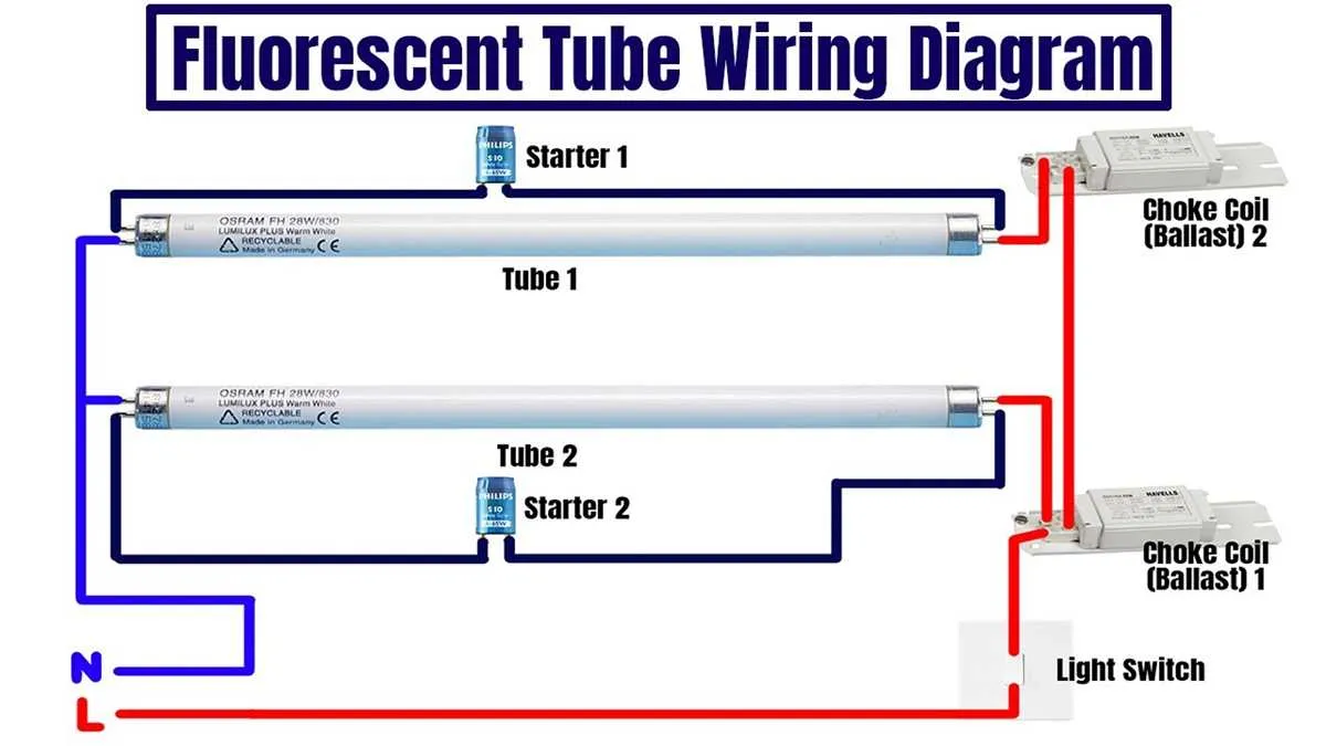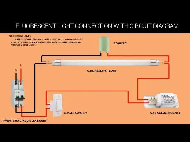
Begin by connecting the live conductor to one terminal of the electromagnetic switch. From the opposite terminal of the switch, extend a path to one pin of the first lighting unit. Pair this with a return from the adjacent pin, looping through the glow starter before completing the circuit at the neutral line.
For models utilizing dual-pin connectors on each end, ensure each side is properly bridged with parallel conductors. The heating filaments require precise pairing to initiate arc discharge, especially in setups without instant-start gear. Position the preheat trigger close to the input side to optimize response time.
Tip: When installing a pair of linear emitters, use a series choke configuration only with compatible fixtures. High-frequency alternatives demand electronic controllers with built-in overcurrent protection and pre-programmed start cycles.
Warning: Do not bypass thermal protection elements in the control module. These are essential for maintaining long-term safety and preventing cathode degradation.
Connection Layout for Gas-Discharge Tube
Always disconnect power before assembling the circuit. Ensure the ballast matches the tube’s power rating and type (e.g., T8 or T12). For a typical single-lamp configuration using an electromagnetic choke, follow this setup:
- Connect one terminal of the mains live wire to one side of the choke.
- Join the opposite end of the choke to pin 1 of the tube holder.
- From pin 2 on the same side, wire to one terminal of the glow starter.
- The other terminal of the starter links back to the neutral wire.
- Connect pins 3 and 4 (opposite side of the tube) directly across mains live and neutral, completing the loop.
For a dual-lamp setup with a magnetic inductor:
- Each lamp should have its own starter.
- Use two chokes, one per unit.
- Connect live to the first inductor, then to the initial pin of lamp A.
- Wire through starter A and back to neutral.
- Repeat the same structure for lamp B on a parallel branch.
Secure all connections using terminal blocks. Verify voltage and frequency compatibility (e.g., 220V, 50Hz). For high-frequency electronic controllers, match pin assignments based on manufacturer schematics, as layouts vary widely.
How to Identify Terminal Connections on Ballasts
Start by examining the label printed directly on the component’s casing; it typically includes a schematic with terminal identifiers such as L for line, N for neutral, and colored leads like blue, red, or yellow connected to lamp holders.
Use a multimeter set to continuity mode to verify internal links between terminals. For electronic variants, check for continuity between output wires and ensure no connection exists to the input side.
Follow wire color conventions: blue and red leads commonly connect to opposite ends of the lighting tube, while yellow ones often serve as a shared return. These may vary by model, so cross-reference with printed schematics.
Disconnect power before inspection. Remove the cover and trace each conductor from the terminal block to its destination using insulated tools. Look for factory labels stamped on the enclosure or terminal board, often marked as L, N, or COM.
Note physical layout: older magnetic types usually have screw terminals, whereas modern compact units often use quick-connect blades or pigtail leads. Never assume function by color alone–always verify against the specific component chart.
Steps to Wire a Single Tube with Starter
Connect the phase wire directly to one pin of the lamp holder on the input side. This terminal will also link to one leg of the ignition module.
Bridge the opposite pin of the same lamp holder to one end of the starter. Use insulated copper wire rated for 250V or higher.
Attach the neutral line to the second socket on the output side. This connection finalizes the circuit path back to the power source.
Insert the discharge tube firmly into both holders, ensuring tight metal contact to avoid arcing. Then place the starter into its slot securely.
Verify component ratings: ensure the starter is matched to the power level of the tube, typically marked with compatible wattage (e.g., 18W, 36W).
Check ballast placement between the phase line and the input holder. This coil must be rated to limit current to safe operating levels.
Before powering up, inspect all terminals for secure attachment, and confirm no exposed conductors are present to avoid shock or short-circuiting.
Troubleshooting Common Fluorescent Wiring Issues

Start by verifying that the power supply delivers a stable 120V or 240V, depending on the system rating. Use a multimeter at the input terminals to confirm voltage presence before proceeding.
If the fixture fails to activate, check the starter or ignitor for continuity. A failed starter typically prevents the arc from forming across the electrodes. Replace if resistance is infinite.
Inspect the control unit (commonly called the ballast) for discoloration, bulging, or odor, indicating thermal damage. Measure output voltage to the tube sockets; absence suggests a failed internal capacitor or open circuit.
Ensure all socket connections are secure and corrosion-free. Clean terminals with contact cleaner and reseat the tube ends to ensure firm contact with the holders.
Test the tube with a known-working unit. If it illuminates elsewhere, the issue lies in the circuit, not the tube itself. Swap components systematically to isolate the fault.
Check for ground faults between metal housing and neutral. Unwanted continuity could trigger safety devices or interfere with operation. Use insulation testers to detect leakage paths.
For units using electronic controllers, inspect PCB traces for cracks and cold solder joints. Reflow suspicious joints with fresh solder to restore connectivity.