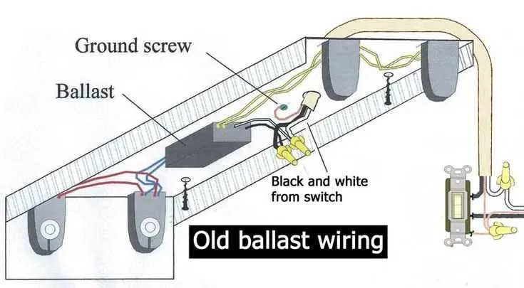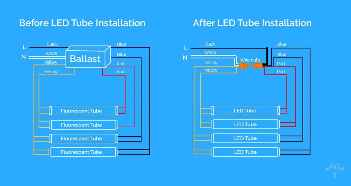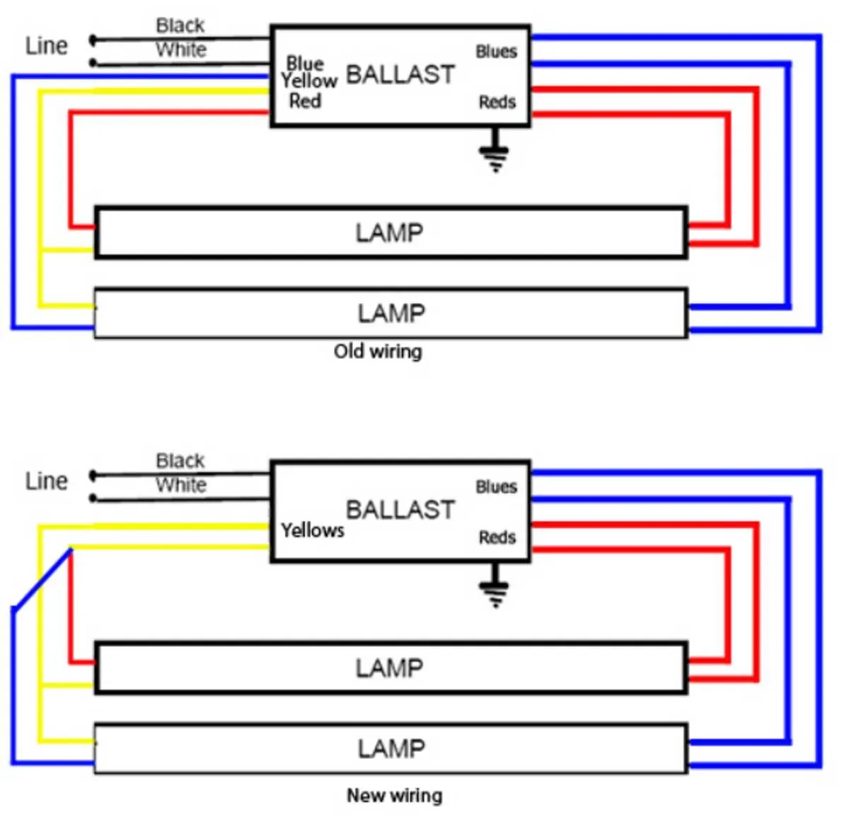
When setting up a multi-lamp setup, correct connection of each component is crucial to ensure proper functionality. The method of linking the lighting components involves specific terminals that handle power distribution and regulation. Each unit needs to be paired with a matching electrical driver to ensure uniform performance across all four elements.
Start by connecting the main power source to the central terminal that serves as the input. From here, distribute the power evenly to each individual unit, taking note of the polarity for correct flow. Ensure that each connecting terminal is securely fitted to avoid loose connections, which could lead to operational issues.
It’s essential to keep in mind the specific voltage ratings for each lamp. For systems designed to operate with higher energy loads, use wire gauges that can handle the increased current. Pay close attention to the recommendations for each unit’s electrical specifications to prevent overheating or damage.
Once the wiring setup is complete, confirm that all links are firm and stable. Conduct a test to ensure that each lamp receives the required power output and operates without flickering. If any element shows signs of instability, check for wiring faults or power distribution errors.
Electrical Configuration for Four-Light Setup

For a four-light fixture setup, connect the power supply to the central terminal of the controller. Ensure the proper voltage rating for the fixture’s electrical components to avoid overloads. Each lamp’s terminal should be connected in a parallel circuit, where one end of the wiring runs to a designated terminal block, and the other connects to the respective control input.
When linking the four lamps to the transformer, allocate the positive leads of each fixture to a common terminal, ensuring a consistent power distribution. The negative connections from each unit should be properly grounded or linked to a shared ground wire, adhering to local safety regulations.
To prevent flickering or voltage fluctuations, make sure the ballast’s capacity matches the power requirements for all connected units. The wiring setup should be checked for any potential short circuits, especially around the distribution points where wires are split to each lamp.
Lastly, double-check the connections for tightness and secure them with appropriate clips or connectors to minimize the risk of loose wiring, which could lead to operational issues.
Understanding the Wiring Connections for Four-Lamp Systems
Ensure that you properly identify the terminals on the electrical unit. For a setup involving four light sources, it’s crucial to connect the correct leads to the appropriate terminals on each fixture. The first step is to connect the input power wires to the primary terminal block, ensuring that the voltage rating matches the fixture specifications.
Input Power Connections: Begin by attaching the live and neutral wires to their corresponding connectors. Verify that the grounding wire is securely attached to the designated grounding terminal. This step is essential for safety and proper operation.
Lamp Terminals: Each light should be connected to the output terminals in the proper order. Typically, each connection should be made between the fixture and the device’s control mechanism, ensuring that the circuit is continuous and that there are no loose or exposed connections.
Checking Resistance: Once all connections are made, it’s advised to test the continuity of each connection. Use a multimeter to check for continuity between the input terminals and the output connections to confirm that all components are correctly linked. A lack of continuity may indicate a loose connection or a malfunctioning component.
Power Control Settings: Adjust the settings to control the intensity or voltage to each of the four units. Ensure that each fixture is receiving the required amount of power and that the circuit is balanced across all terminals.
Safety Precautions: Always verify the unit is not powered before making any modifications to the connections. If any component appears faulty or improperly wired, disconnect the system and troubleshoot the setup before re-energizing the circuit.
Common Issues and Troubleshooting for Four-Lamp Fixtures

Ensure the correct voltage is being supplied to the unit. Mismatched power sources can cause flickering or non-operation. Check your power source’s output using a multimeter.
- Incorrect Connections: Double-check each terminal to confirm it is securely connected. Loose or improperly connected terminals are a frequent cause of malfunction.
- Overloaded Circuit: If too many fixtures are connected to a single power line, it may result in insufficient current, causing the system to fail. Ensure your circuit is rated for the total load.
- Damaged Components: Examine all components for physical damage. Burned or scorched parts should be replaced immediately.
- Improper Grounding: Verify that the system is properly grounded. A poor connection can lead to short circuits or inconsistent performance.
- Defective Starter or Ignitor: A malfunctioning igniter can prevent the fixture from starting correctly. Replace this component if the unit fails to activate or flickers intermittently.
Testing continuity for each component in the system can identify faulty parts, helping pinpoint the root cause. If the issue persists after addressing these common points, consult the manufacturer for further troubleshooting guidelines.
Step-by-Step Guide to Installing a 4-Light Control System
Start by disconnecting the power to the system. Ensure the circuit is turned off before proceeding with any connections. This step is crucial to avoid electrical hazards.
Next, mount the central unit securely in a location that allows easy access to its terminals and connectors. The control module should be placed in a stable position, minimizing the risk of mechanical damage.
Connect the main power lines to the appropriate input terminals on the unit, ensuring the live, neutral, and ground wires are correctly aligned. Verify that all connections are tight to prevent any potential short circuits.
For each of the four output channels, attach the wires leading to the respective fixtures. Double-check that each wire is matched with the proper terminal to ensure consistent performance across all connections.
Once the connections are made, carefully mount the light fixtures in their designated locations. Ensure they are securely fixed and that no wires are pinched or exposed, as this can lead to short-circuiting or other safety risks.
After securing the fixtures, reconnect the power and test each output to verify proper operation. If any fixture fails to activate, inspect the corresponding connection and troubleshoot if necessary.
Finally, if everything functions as expected, perform a final check of all connections and ensure there are no exposed wires or loose terminals. Power on the system, and the setup should be fully operational.