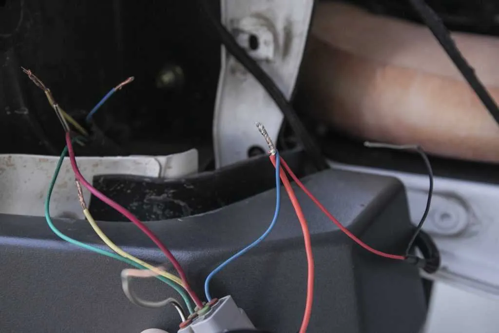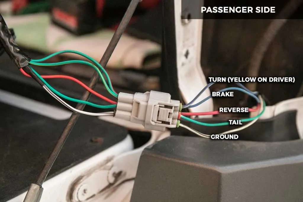
If you’re experiencing issues with the rear illumination system of your vehicle, understanding the connection map is crucial. First, locate the power source for the back lighting system–typically the fuse box or relay in the engine compartment or under the dashboard. It’s important to check that the wiring is intact and free from corrosion or damage. A faulty connection can prevent proper function or cause intermittent lighting problems.
Next, verify the specific terminals involved in your rear lighting components. Ensure that all connections are tightly secured, especially those leading to the brake, indicator, and reverse lamps. A poor connection can lead to a variety of lighting failures, from dimming to complete power loss. It’s essential to cross-check the ground wire, which plays a key role in ensuring stable function across all bulbs.
In cases of electrical malfunction, using a multimeter to test the continuity of each wire will help pinpoint any broken circuits or short circuits. Always remember that for safety, disconnect the power before making any repairs or adjustments. Once you’ve identified the issue, you can trace the connections to replace or repair any faulty sections, restoring proper lighting functionality.
Electrical Connections for Rear Illumination System
To ensure proper function of the rear signaling components, verify that each circuit is connected according to manufacturer specifications. Start by confirming that the ground wire is securely attached to a clean, corrosion-free metal part of the vehicle. The positive wire leading to the braking system should be checked for continuity to ensure it activates the rear lamps upon brake pedal engagement. Additionally, the reverse signal line must be routed directly to the reversing switch, which is typically located near the transmission. When wiring the turn signal circuit, ensure that the switch is connected to the rear blinker module for accurate operation.
For enhanced longevity and safety, use high-quality connectors and avoid splicing wires without proper insulation. Pay special attention to the color-coding system used in the harness to avoid cross-connection errors. In most cases, a standard 12-volt power supply is sufficient for the system, but always check the vehicle’s manual for specific voltage requirements. Properly securing the cables with plastic clips helps reduce wear from vibrations and prevents accidental disconnections.
If experiencing issues with lighting operation, inspect the fuses associated with the rear components. Replace any blown fuses with the correct amperage rating to prevent damage to the electrical system. If the problem persists, test the individual bulbs and connections to pinpoint any fault or corrosion in the circuit. Regular maintenance of the system ensures consistent performance and reduces the likelihood of electrical failures.
Understanding the Pinout of Rear Lamp Connectors

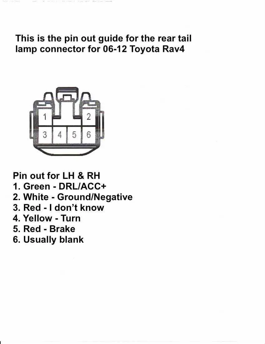
When working with rear lamp connections, pay close attention to the pin assignments to avoid incorrect wiring. The most common pins are typically assigned to brake signals, reverse lights, and ground connections. It’s crucial to identify the correct terminal for each function to ensure proper operation of all lighting features. In most cases, the ground pin is positioned at one end of the connector, often marked with a black wire. The brake signal pin is frequently found in the center of the connector, while the reverse light pin is located next to it, but with a distinct color, often white or green.
Consult the vehicle’s wiring schematic to verify the exact positions. Most connectors will have a labeled chart on the side for easy reference. In some instances, you may also find an additional terminal for turn signals, which could be in the form of an amber light. For optimal results, use a multimeter to double-check voltage outputs on each terminal before finalizing any connection. Always ensure the correct polarity when dealing with power connections to avoid damaging electrical components.
If your vehicle uses a multi-pin connector, identifying each pin based on its wire color and function is crucial. Cross-check with manufacturer specifications or a detailed schematic to confirm the pinout. In some models, connectors may have different configurations depending on the production year or trim level, so always ensure compatibility with your particular model.
Step-by-Step Guide to Diagnosing Electrical Issues in Rear Illumination Systems

Start by checking the fuse box for any blown fuses linked to the rear illumination circuits. A blown fuse often indicates a short circuit or excessive current draw.
- Step 1: Locate the fuse associated with the rear bulbs, typically marked on the fuse panel cover. Use a multimeter or visual inspection to confirm its condition.
- Step 2: If the fuse is intact, proceed by checking the bulb sockets for signs of corrosion or loose connections. Corrosion can interrupt the flow of electricity, causing intermittent or no illumination.
- Step 3: Use a circuit tester to verify power at the bulb socket. If no voltage is present, inspect the ground connections at the rear assembly. A poor ground often leads to malfunctioning lights.
If voltage is present but the bulb does not illuminate, the bulb itself may be faulty. Replace with a new bulb and test again.
- Ensure the replacement bulb is the correct type and voltage rating for the system.
- Consider using a dielectric grease on the socket to prevent future corrosion.
For further diagnosis, trace the wiring back to the power source to detect any breaks, frays, or chafed wires that may have occurred. A break in the conductor can disrupt the current flow.
- Step 4: Inspect the connectors along the wire for signs of wear. Use a multimeter to check for continuity. If a wire is broken or has too much resistance, it will need replacement.
- Step 5: If all connections are intact, the issue may lie within the switch controlling the system. Test the switch to ensure it is sending power when engaged.
Lastly, check the vehicle’s control module if applicable. Modern systems sometimes route power through electronic controllers, which can fail and disrupt the electrical path.
How to Install Aftermarket Rear Lamps Using the Connection Scheme

Start by disconnecting the vehicle’s battery to prevent any electrical mishaps. Locate the original fixture’s power connectors and carefully remove the old components from the housing. Be cautious not to damage the socket or wires. Before proceeding, make sure the new assembly matches the original in both connector types and size.
Next, identify the power leads for the brake, reverse, and indicator functions. Each wire will correspond to a specific function in the aftermarket unit. Use the provided schematic to ensure you correctly match the wires to the new assembly. If the new unit doesn’t come with a matching plug, you will need to manually crimp or splice the wires using a suitable connector or terminal.
Secure the new setup into the mount, ensuring it fits snugly and aligns with the vehicle’s body. Double-check all connections to confirm proper contact and no loose or exposed wires. Once in place, reinstall any securing screws or fasteners to hold the assembly firmly in position.
Reconnect the vehicle’s battery and test the new components. Check the brake, reverse, and turn signal functions to ensure they work as expected. If any of the lights do not operate correctly, verify the connections and troubleshoot the wiring to confirm proper installation.
Tip: Always use high-quality connectors to ensure a secure and durable connection. Avoid cutting corners with cheap connectors, as they may lead to malfunctioning over time.