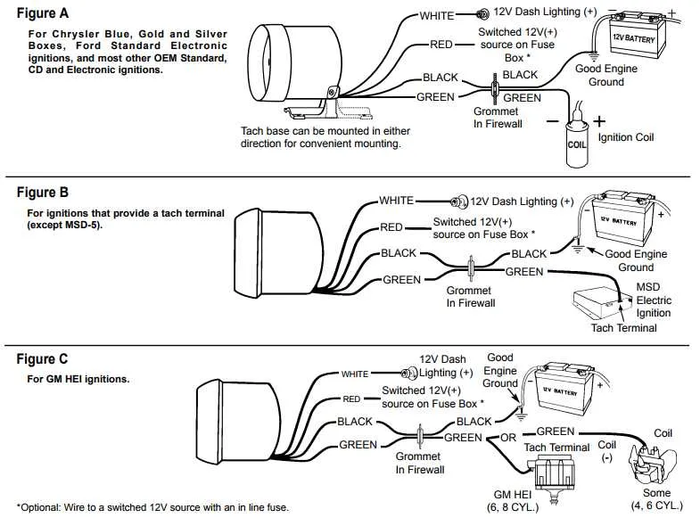
To correctly set up a 4-wire measurement device, start by identifying the four essential connections: power supply, ground, signal output, and trigger input. Each of these plays a vital role in ensuring proper operation. The power input should be connected to a stable DC voltage source, typically 12V or 24V, depending on the device specifications. Grounding ensures the unit is properly referenced to the electrical system, preventing potential interference.
The next connection, the signal output, is used to send data to the measurement unit, often as a pulse signal that varies with rotation or speed. This connection is typically linked to an input port on the control or display system. The trigger input, often the most misunderstood, works as the synchronization point, ensuring that the device’s reading starts or resets at the correct timing intervals.
Ensure each connection is secure and free of interference by using the appropriate connectors and insulation materials. Pay close attention to the manufacturer’s manual for exact pinout information to avoid any errors in setup. Improper connections could lead to incorrect readings or, in some cases, permanent damage to the device. Once all connections are made, conduct a test to confirm proper function before proceeding to operational use.
Important Tip: Always check the voltage and current ratings specified for each wire and component. Overloading any connection can result in failure or erratic performance.
4-Pin Meter Connection Setup
To connect a 4-pin monitoring device properly, follow the steps below to ensure accurate functionality:
- First Pin (Power Source): Connect this to a 12V or 24V DC power supply, depending on your system’s requirements. Ensure stable voltage to avoid malfunction.
- Second Pin (Ground): Attach to the ground or negative terminal. This pin ensures the circuit’s return path, completing the electrical flow.
- Third Pin (Signal Input): This is the input for the data stream from your engine or machinery. Typically, it’s a pulse or frequency signal that represents the operational speed.
- Fourth Pin (Output or Feedback): Use this pin to send data or readings to other connected systems or display units. This allows the monitoring unit to relay the current readings for further analysis.
For best results, double-check connections before powering up the system. Use insulated terminals for safety, and ensure all contacts are tight to prevent signal loss. Keep the input and output wires separate to avoid interference between signals.
Identifying the Function of Each Lead in a 4-Lead Measurement Device

First lead: This is typically the power source input, which delivers the necessary voltage to activate the system. Ensure it is connected to a steady 12V supply for proper operation.
Second lead: Serves as the ground. It completes the electrical circuit and should be connected to the vehicle’s chassis or negative terminal of the battery.
Third lead: This is the signal output, transmitting the frequency that corresponds to the rotational speed. It sends pulses based on the revolutions, which the receiving unit processes to display the speed.
Fourth lead: Functions as the input for calibration or control settings. It might be linked to the system for adjusting the sensitivity or range depending on the device’s design.
Note: Verify the color-coding of each lead in your setup, as it can vary by manufacturer. Always consult the specific instructions for accurate identification and ensure secure connections to avoid malfunctions.
Step-by-Step Guide for Connecting a 4 Wire Tachometer to Your System

1. Begin by identifying the four terminals on your device. These are usually labeled for easy reference: power, ground, signal, and output.
2. Connect the power terminal to a stable 12V DC power source. This will provide the necessary voltage to operate the unit.
3. The ground terminal should be linked to a reliable ground point on your system. Ensure this connection is solid to avoid electrical interference.
4. The signal terminal typically requires connection to the engine or motor’s output, which sends the rotational data. Verify the correct source to ensure accurate readings.
5. Attach the output terminal to the monitoring or display unit, where you need to see the rotational data. This allows the results to be shown in real-time.
6. Once all connections are made, power up the system and check the readings. Make adjustments if necessary to ensure proper functionality.
Troubleshooting Common Issues with 4 Wire Tachometer Setup
Start by checking the power connection. Ensure the positive lead is securely connected to the correct terminal and the ground is properly attached to the vehicle’s frame or a reliable grounding point.
If the reading is erratic or shows no response, inspect the signal input. A weak or interrupted signal can result from poor contact or a faulty sensor. Look for any signs of wear or corrosion at the sensor end and clean or replace if necessary.
Next, verify the connection to the display unit. If it’s not receiving the signal, the display may be faulty or there might be a loose connection at the input terminal. Ensure that all pins are properly seated, and test the connection with a multimeter for continuity.
If the device is showing inaccurate readings, ensure the voltage levels match the specifications. Over-voltage or under-voltage can cause the display to misinterpret data. A voltage regulator can help stabilize the supply.
In case of persistent issues, check for electromagnetic interference (EMI). Devices like motors, alternators, and other electrical components can cause noise. Shielding the affected area or rerouting sensitive connections might reduce this interference.
Finally, ensure the grounding is adequate. A poor ground connection can lead to fluctuating readings or failure to register entirely. Re-check the ground terminal for secure and corrosion-free contact.