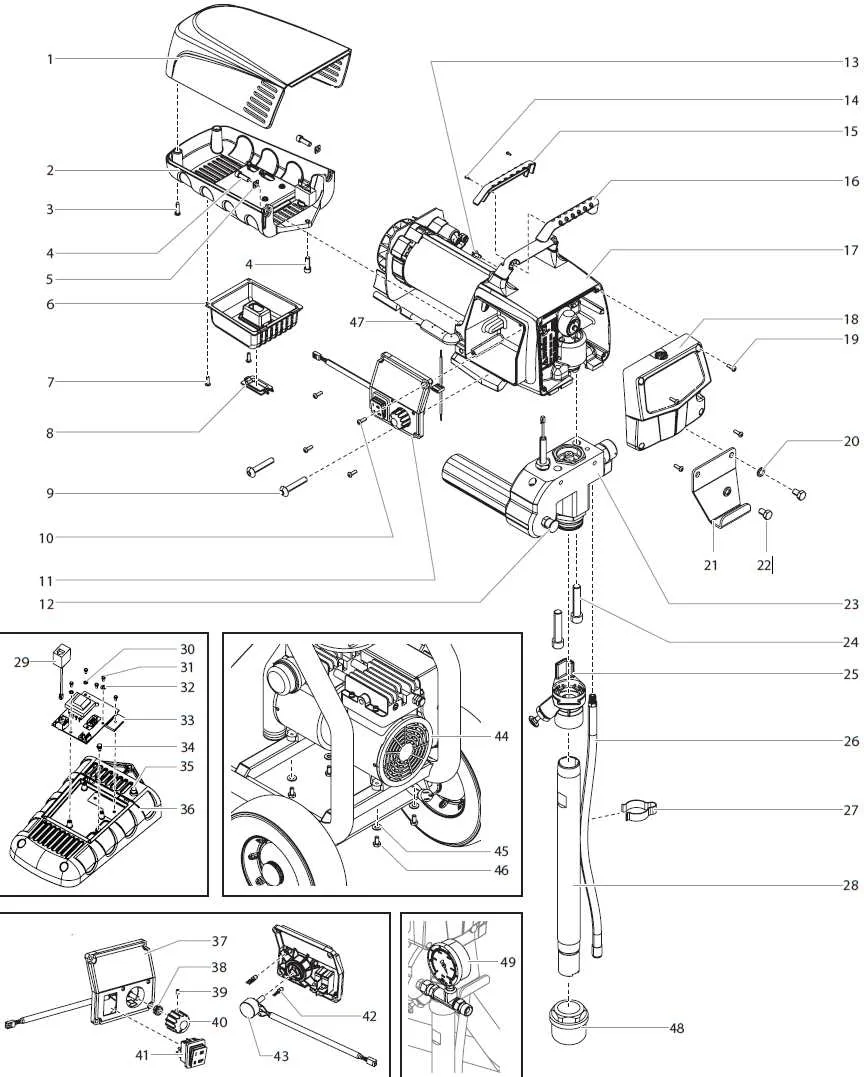
For accurate assembly and maintenance of your equipment, it’s crucial to refer to the detailed component layout provided by the manufacturer. This visual representation offers a comprehensive guide to identifying each individual element and understanding its function within the overall system. Ensure you are familiar with every part’s placement to avoid errors during repairs or modifications.
When working with machinery, always start by examining the specific numbers and references listed next to each part in the chart. These identifiers will allow you to match the required components with those available in the spare parts catalog. Pay attention to the material specifications for each unit, as this can affect performance and durability.
To further streamline your repair process, cross-reference the given component arrangement with the maintenance manual. If possible, make notes on the visual chart, highlighting any wear-prone elements that may need frequent inspection or replacement. This proactive approach reduces downtime and ensures the longevity of the machinery.
Pro Tip: Always keep an eye out for parts marked with specific instructions or warnings–such as torque requirements or special handling guidelines–to prevent issues during reassembly.
Replacement Component Layout

Ensure you have the correct model numbers before purchasing components for your sprayer. Accurate identification is crucial for maintaining efficiency and avoiding unnecessary downtime.
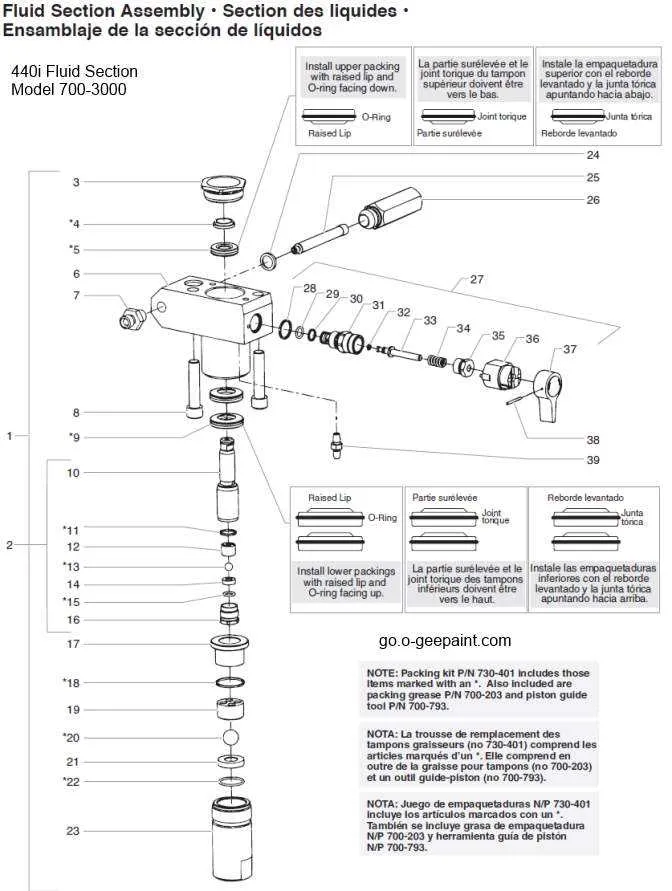
Start by checking the specific assembly sections, such as the pump unit and spray nozzle configurations. These parts must align perfectly to ensure smooth operation. Refer to the exploded view for each section to determine where each piece fits, focusing on seals, filters, and hose connections.
For the fluid delivery system, inspect the pressure control valves and flow regulators. These elements are vital for consistent spray pressure. Use the schematic to double-check the compatibility of replacement seals and gaskets in these areas.
The spray gun assembly, including its trigger mechanism and nozzle options, requires particular attention. Identify any wear on the moving parts, and compare them with the diagram for exact matching to avoid leaks or inconsistent spraying patterns.
In the case of the air cap assembly, ensure that all components are properly secured to avoid any air loss, which can affect performance. Refer to the sectional view of the cap to confirm all parts are correctly installed and positioned.
Lastly, check all mounting hardware and bolts. The support frame can become unstable if the bolts are not tightened according to specifications. Make sure you match the correct torque values as shown in the detailed layout to avoid damage to the frame or internal components.
Identifying Key Components in the Titan 440 Parts Diagram

When analyzing the breakdown of the mechanical system, focus on recognizing the core elements responsible for the device’s functionality. Start with the engine assembly, which typically consists of a motor housing, internal gears, and cooling components. Pay attention to the pumps and valve groups, as these are crucial for fluid regulation and pressure maintenance. Identify the control panel wiring to understand electrical connections, as they play a key role in operational management.
The seals and gaskets should be examined closely for their placement within the structure, ensuring proper sealing during operation. The frame assembly is another vital component that supports the entire system, and its strength is paramount for overall durability. Additionally, the bearing and shaft systems are central to the device’s movement, transferring power with minimal friction.
Take special note of circuit protection units in the electrical sections, as these prevent overloads and enhance the system’s longevity. A thorough examination of the control valves ensures smooth operation by regulating the flow of fluids within the machinery. By focusing on these primary units, you’ll gain a clearer understanding of the overall mechanics at play.
How to Read and Use the Diagram for Maintenance Tasks

Start by locating the specific component you need to repair. Identify the section in the schematic that corresponds to this part. This will often be highlighted or labeled for easy navigation. Once you find it, pay attention to the surrounding elements and connections to understand how it interacts with the rest of the system.
- Examine the flow paths between parts to see how they work together. This will guide you in pinpointing issues related to fluid or air passage.
- Note the color coding or numbering, which may indicate the sequence or order in which parts are assembled or disassembled.
- Look for symbols that represent seals, gaskets, or O-rings. These are crucial for understanding the sealing mechanism in the setup.
Once you’ve identified the faulty part, consult the reference number or description. Compare this with the manufacturer’s manual or online resources to find specifications, compatibility, and replacement procedures.
- For pumps, check the flow diagrams to ensure that all valves are operating correctly, and seals are intact.
- If it’s a nozzle or sprayer, cross-reference with adjustment and assembly notes to ensure proper alignment and pressure settings.
- Take special care with any moving or high-pressure components, as these require precise reassembly and testing after repair.
For troubleshooting, use the step-by-step breakdown to isolate potential issues. Start from the input or power source and move systematically through to the output. This method reduces the chance of missing an underlying fault.
Common Issues and Troubleshooting Using the Titan 440 Parts Diagram
Start by checking the spray pump for blockages or damage. If you notice a weak or inconsistent spray pattern, inspect the fluid intake valve for debris. Clean or replace it as needed to restore proper function.
If the machine doesn’t start, verify the power supply and motor connections. A loose or disconnected wire could be the culprit. Use the provided schematics to trace the electrical wiring and ensure everything is securely in place.
In case of leakage, inspect the seals and gaskets. Over time, these components can wear out or become brittle. Replace any compromised parts to prevent further fluid leakage.
For reduced pressure, examine the piston and cylinder assembly. If the piston shows signs of wear, replace it immediately to avoid performance issues. Additionally, check the pressure regulator settings and adjust as needed to maintain optimal pressure levels.
If you’re experiencing excessive noise, lubricate the moving parts, especially the motor bearings. Refer to the maintenance instructions in the manual for the correct lubrication schedule and recommended materials.
For spray tip clogs, remove the nozzle and flush it with warm water to dislodge any blockages. Regularly cleaning the spray tip can prevent future clogging and ensure a steady, even spray pattern.