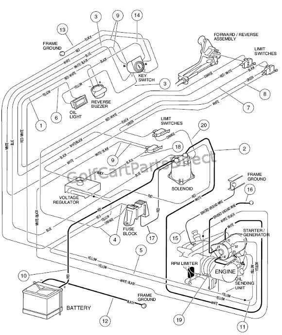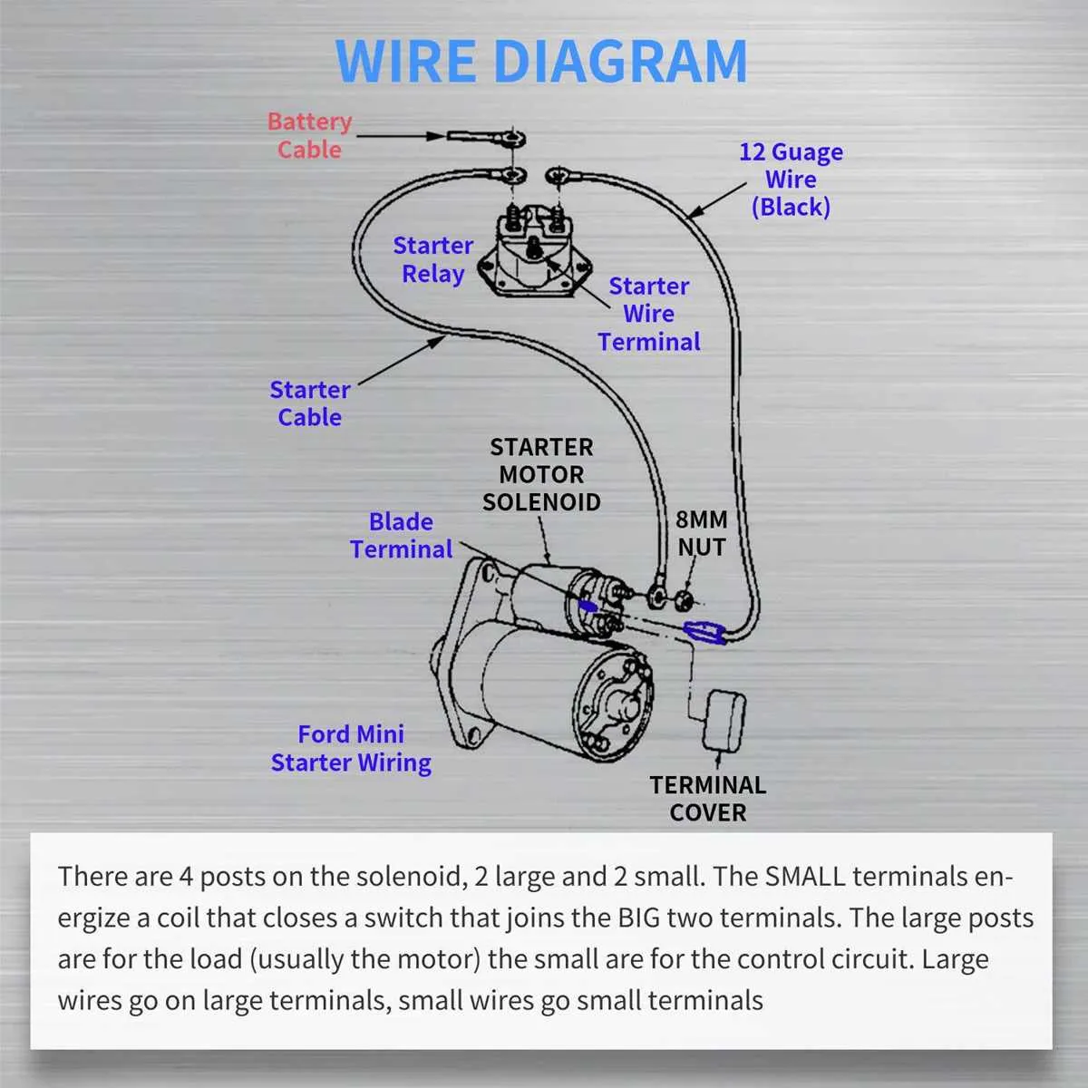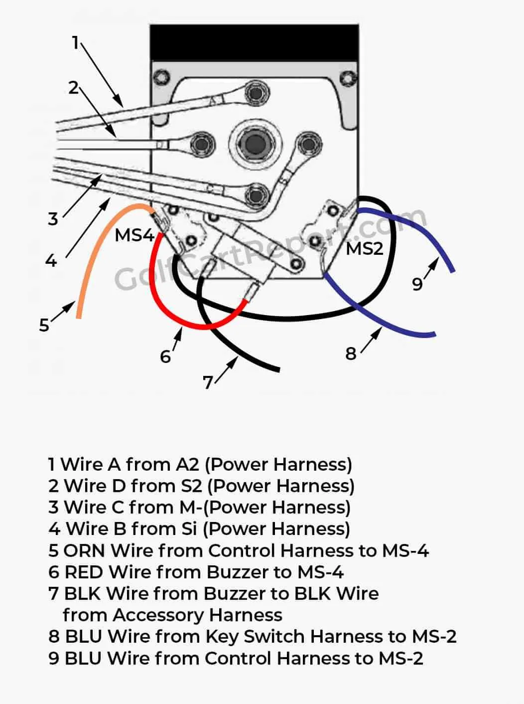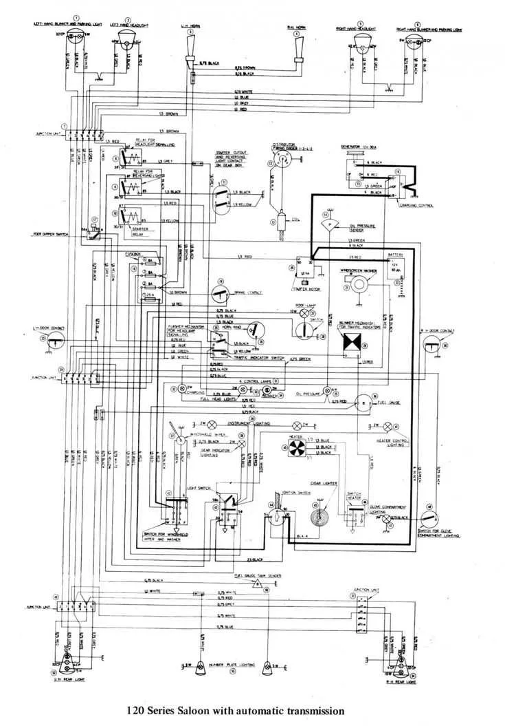
When working on the power setup of your vehicle, it’s crucial to have a clear understanding of how the components interact. A well-organized power scheme can make troubleshooting and modifications much easier, especially when addressing issues related to power distribution, switches, or motor connectivity.
Start with the battery connections: Ensure that all cables are securely connected, with no signs of corrosion. The positive and negative terminals should be checked regularly to prevent electrical failures. If your vehicle experiences power loss, the first thing to check is the battery voltage and the integrity of its wiring.
Check for continuity: Use a multimeter to verify that all wires carry current without interruption. This will help identify any potential short circuits or broken wires, particularly in the areas near the motor and control systems.
Pay attention to the motor’s wiring as well. It’s essential to know the layout of the motor’s input and output connections, as faulty wiring can lead to overheating and performance issues. Inspect the motor for wear and tear, and be ready to replace any parts that show significant damage.
Another critical aspect is understanding the fuse box and relay connections. A blown fuse can often be the cause of power issues, and knowing the exact fuse specifications and relay functions will save time during repairs. Always replace a blown fuse with one of the same rating to prevent further damage.
Wiring Overview for Utility Vehicle Systems
For a seamless operation of your vehicle, ensure all connections from the battery to key components are secure. Start by checking the main power supply to ensure the battery provides adequate voltage, typically 36V or 48V, depending on your model. The voltage regulator plays a crucial role in stabilizing power for the control module and motor, so inspect it regularly for any signs of wear or corrosion.
Verify that all grounds are correctly connected, particularly those linked to the frame and motor. A poor ground connection can cause erratic performance or failure to start. The throttle controller and brake switch must also be in proper condition for accurate response. If your unit includes a reversing switch, ensure the wiring is intact and there is no damage that could cause malfunctioning or unexpected behavior.
For diagnostic purposes, use a multimeter to check continuity across key circuits, especially the motor and controller connections. If the unit operates intermittently, a loose connection at the controller or solenoid could be the cause. Ensure the wiring harnesses are undamaged and free from any sharp bends or abrasions.
Lastly, for high-performance models, review any modifications that could impact the system’s original wiring. Non-standard alterations might require custom adjustments to the power distribution network to maintain efficient operation.
How to Read an Ezgo Golf Cart Wiring Schematic

Start by identifying the power source. Locate the battery connections, ensuring the voltage readings align with the system requirements. From the battery, follow the main power wire to the controller, noting any fuses or circuit breakers along the path. These components protect the system from overloads, so check for proper ratings.
Next, focus on the motor and its connections to the controller. Understand the wiring leading to the field windings and armature, as these parts determine the vehicle’s speed and torque. Pay attention to color codes, as they help distinguish between various circuit paths. For instance, red typically represents positive power, while black or green signals ground connections.
Track each wire’s destination to understand the function of each component. Verify the continuity of connections using a multimeter. Ensure that all sensors, like the throttle position or brake switch, are wired correctly and match the schematic indications.
For systems involving lighting or other accessories, locate the corresponding circuits and confirm their integration with the main power system. These should be isolated with dedicated relays or fuses to prevent overloads. Check any secondary wiring for accuracy and proper routing.
Finally, cross-check your work by turning on the system and testing the components step by step. Ensure that each part activates as expected, confirming that the wiring matches the schematic and that there are no short circuits or faulty connections.
Identifying Key Components in the Ezgo Golf Cart Electrical System

Battery Pack: The primary source of power. Ensure the voltage matches the system’s requirements, and check for any corrosion on terminals that could impede power flow.
Controller: The brain of the setup. It regulates power distribution to the motor. If there’s an issue with acceleration or response, inspect the controller for signs of damage or overheating.
Motor: The component that converts electrical energy into mechanical movement. A malfunction could be due to worn brushes or internal short circuits. Look for unusual noises or lack of power delivery.
Solenoid: Acts as a high-voltage relay to connect the battery pack to the rest of the system. It can fail due to heat buildup or defective contacts. Test it by checking for continuity when the system is engaged.
Fuses: Protect the system from overloads. If there’s no power or intermittent functioning, inspect the fuse box. Replace any blown fuses and ensure the correct ratings are used.
Wiring Harness: Carries signals and power between components. Check for any signs of wear, fraying, or loose connections. A broken wire could cause a short or loss of power to key parts.
Charger: Ensures the battery pack is consistently replenished. Test the charger’s output voltage to confirm it’s providing the right charging current. If the battery doesn’t charge properly, the charger might be defective.
Throttle Switch: Responsible for controlling speed. A faulty throttle can result in erratic speed control or a complete lack of response. Test the throttle switch for consistency in readings and resistance.
Troubleshooting Common Power System Issues Using the Wiring Guide

If your vehicle fails to start or exhibits abnormal behavior, it’s essential to first check the primary components for any faults. Here’s how to identify and resolve common issues by referencing the wiring guide.
- Dead Battery: Inspect the battery voltage with a multimeter. A healthy battery should read around 12.6 volts. If it’s lower, attempt a recharge. If the problem persists, consider replacing the battery.
- Fuses and Relays: A blown fuse or malfunctioning relay can cut off power to critical systems. Check the fuse box for any signs of damage and replace any blown fuses. Relays should be tested for continuity using a multimeter.
- Loose or Corroded Connections: Examine the connectors for any signs of corrosion or loose fittings. Corrosion can cause unreliable connections, leading to intermittent power loss. Clean connections and tighten them as necessary.
- Controller Faults: If the system doesn’t respond when pressing the pedal, there might be an issue with the controller. Inspect the wiring between the controller and motor for signs of wear. If necessary, test the controller with an ohmmeter to check for faults.
- Motor Issues: A motor that doesn’t run or operates sporadically may have internal damage or connection problems. Check for continuity across the motor terminals. If there’s no continuity, the motor may need repair or replacement.
- Throttle Problems: If the vehicle doesn’t accelerate correctly, inspect the throttle sensor wiring and ensure the pedal mechanism is functioning smoothly. A misaligned or faulty throttle sensor could be the cause of the issue.
Following these steps and cross-referencing them with the wiring guide can help you pinpoint the root cause of most problems in the system.