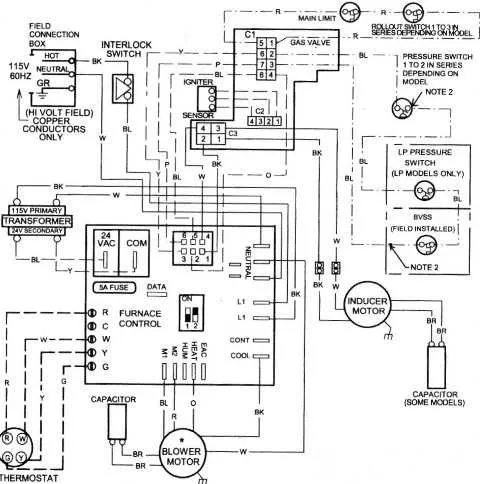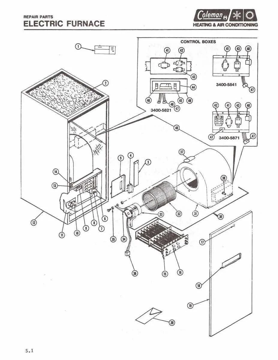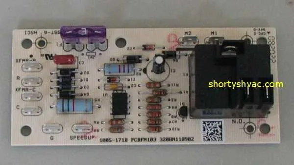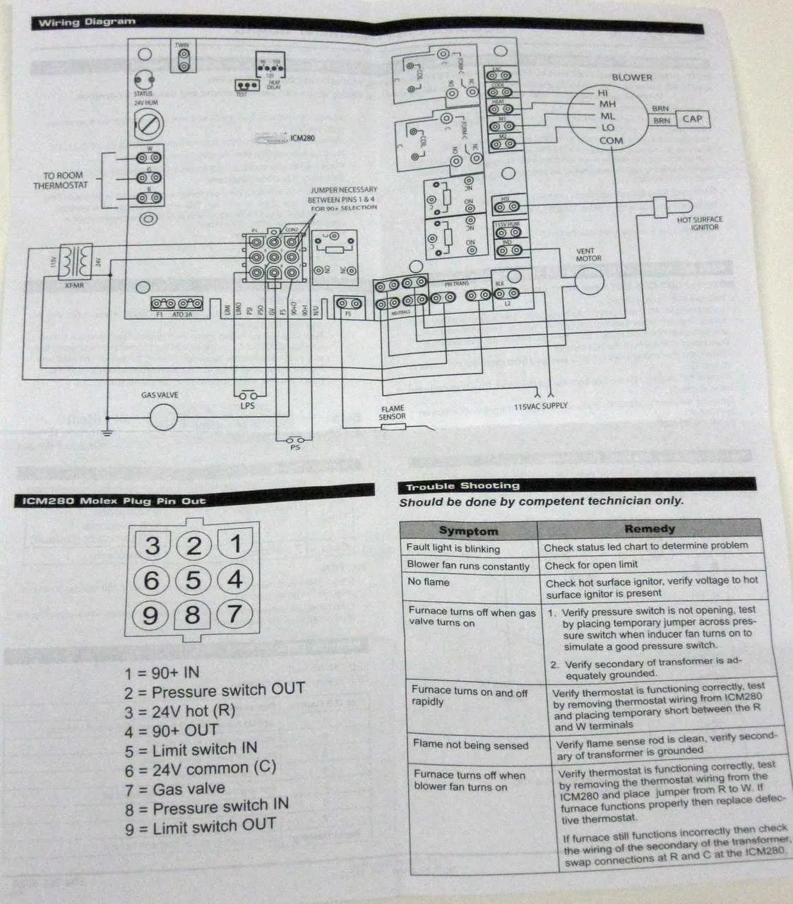
When troubleshooting or installing a heating system, understanding the precise electrical connections is crucial for proper functionality and safety. Each component, from the control board to the power supply, must be wired according to the manufacturer’s specifications. Begin by confirming the voltage and wire gauge to ensure compatibility with your heating equipment.
Verify the transformer connection: This is a critical step to ensure that the correct voltage is supplied to the control system. A common issue arises when the transformer is not properly wired, leading to faulty operation of the system. Ensure that the transformer outputs 24V for control purposes and is connected securely to the circuit board.
Check for proper grounding: Grounding is often overlooked but is necessary for safety. Improper grounding can lead to electrical surges or even fires. Make sure that the ground wire is connected to the designated terminal on the system’s control board.
Identify and label wire connections: Label each wire according to its specific function–whether it’s for the blower motor, thermostat, or igniter. This will help with future maintenance and troubleshooting. Always double-check the wire connections before powering up the system.
Wiring Connections for HVAC Systems
Ensure proper connection of the components for efficient system operation. Start by confirming that all wires are securely fastened to the terminals, particularly for the control board. For maximum safety, always disconnect power before working on electrical components.
The following table outlines key connections and their corresponding functions:
| Terminal | Connection | Function |
|---|---|---|
| R | Red Wire | Power supply (24V) |
| C | Blue Wire | Common ground for thermostat |
| W1 | White Wire | Heat signal from thermostat |
| Y1 | Yellow Wire | Cooling signal (if applicable) |
| G | Green Wire | Fan control signal |
| O/B | Orange or Black Wire | Reversing valve control (heat pump) |
Double-check each connection for compatibility with your system specifications. Ensure wire insulation is intact to prevent short circuits or electrical hazards.
Test system operation once all connections are made. If issues persist, verify the voltage readings with a multimeter to confirm proper electrical flow.
Understanding the Power Connections in a Goodman Furnace

To ensure proper operation, always confirm the correct voltage and wire placement before powering on. The primary power should be supplied to the control board via the main input terminal. It’s crucial to maintain proper polarity when connecting the line voltage wires, typically marked as L1 (hot) and L2 (neutral). These wires should be securely attached to their designated terminals to avoid electrical shorts.
For safety, use a properly rated circuit breaker to prevent overloading. The ground wire must be securely connected to a reliable grounding point. Inadequate grounding can lead to malfunction or even pose a fire hazard. Ensure that all connections are tight and free of corrosion to maintain reliable power delivery.
The transformer should step down the voltage to 24V for the control system. Double-check the low-voltage connections to ensure that wires to the thermostat and other controls are correctly routed and securely fastened. Incorrect wiring of these components could prevent system activation or lead to improper temperature regulation.
How to Identify and Troubleshoot Common Wiring Issues

Check for loose connections first. Ensure that all terminals are securely tightened. A loose connection can cause intermittent power loss and malfunctioning of components. Inspect terminals for any visible signs of wear or corrosion, which could lead to poor contact.
Test the continuity using a multimeter. Place the probes at both ends of the wire. If the reading is infinite or zero, the wire may be broken or shorted. A continuous circuit should give a reading close to zero ohms.
Verify the voltage supplied to the system. Measure the voltage at the power source and at key points like the control board, thermostat, and ignition components. A low or fluctuating voltage reading often indicates issues with the electrical supply or a faulty transformer.
Inspect for shorts in the circuit. Look for areas where wires may be touching metal surfaces or each other, causing a direct short. This can lead to blown fuses, tripped breakers, or damaged components.
Check for incorrect wire placement. Refer to the manufacturer’s wiring instructions to ensure that all wires are connected to the correct terminals. Misplaced wires can cause malfunctions or prevent the system from starting altogether.
Examine the fuse and circuit breakers. If the system is not receiving power, check for a blown fuse or a tripped breaker. Replace any faulty fuses and reset the breaker as needed, but ensure there are no underlying issues that could cause repeated failures.
Test the control board for signs of damage. If the system isn’t responding to inputs or commands, the control board may be malfunctioning. Look for burnt components or any signs of electrical damage on the board.
Step-by-Step Guide to Wiring a Thermostat

Follow these instructions to wire your thermostat correctly for smooth operation.
- Turn off the power supply: Before starting, disconnect all power sources to avoid any electrical hazards.
- Identify the wire labels: Make sure to clearly identify the labels on the existing wiring. Common labels include R, W, C, Y, and G. Write down the existing connections for reference.
- Connect the R terminal: The R wire should be connected to the R terminal. This wire provides power to the thermostat. If you’re using a multi-stage system, you may have separate R terminals for heating (Rc) and cooling (Rh).
- Connect the W terminal: Attach the W wire to the W terminal, which controls the heating system.
- Connect the Y terminal: Connect the Y wire to the Y terminal. This wire activates the cooling system when the thermostat detects the need for cooling.
- Connect the G terminal: The G wire connects to the G terminal, which operates the blower fan. This is essential for air circulation during heating and cooling cycles.
- Connect the C terminal (optional): If your thermostat requires continuous power, connect the C wire to the C terminal. This is common for modern digital thermostats that need a constant power supply.
- Secure the wires: After all connections are made, double-check the wire connections and ensure they are securely fastened. Loose connections can lead to malfunction.
- Mount the thermostat: Attach the thermostat to the wall mounting bracket, ensuring it is level and aligned with the existing screw holes.
- Restore power and test: Turn the power back on and test the thermostat by adjusting the temperature. Make sure that the heating and cooling systems respond appropriately.
Ensure all wiring is done properly to avoid damage to the system or incorrect functioning. If unsure, consult a professional to prevent any issues.