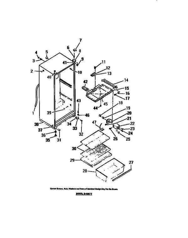
When tackling a malfunctioning cooling unit, having access to a detailed schematic is crucial. The layout helps you pinpoint the exact location of faulty elements, ensuring a swift and accurate repair process. Start by familiarizing yourself with the system’s key components–each one plays a vital role in maintaining optimal temperature control.
By consulting a clear and precise visual guide, you can identify the various sections that require attention, from the evaporator to the compressor. Knowing the arrangement and function of each unit will prevent unnecessary disassembly and reduce the risk of errors. Make sure to cross-reference the schematic with your appliance’s model number for a perfect match.
For an efficient fix: Focus on identifying the most commonly replaced items such as thermostats and fans. Once these parts are located on the diagram, you can proceed with targeted replacements or adjustments without having to disassemble the entire system. Always ensure you are using compatible components for a smooth and safe operation post-repair.
In conclusion: A well-detailed layout is indispensable for anyone looking to repair or maintain their cooling units. Understanding the configuration of essential components allows for faster repairs and helps avoid unnecessary component damage. Always keep an updated copy of the schematic on hand for reference during troubleshooting.
Understanding Appliance Component Layout
For effective troubleshooting, always refer to the detailed visual guide showing the key elements of your unit. Ensure you identify the cooling unit’s fan, condenser coils, and evaporator, as they play crucial roles in the cooling cycle. The compressor, typically located at the bottom, is the heart of the system and should be checked for any signs of wear or malfunction.
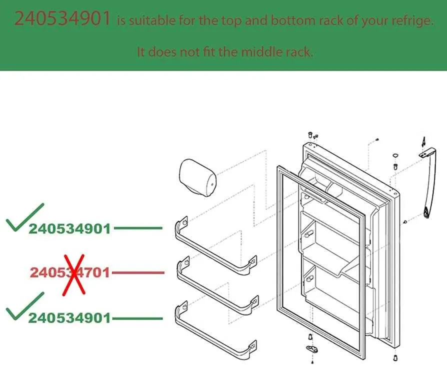
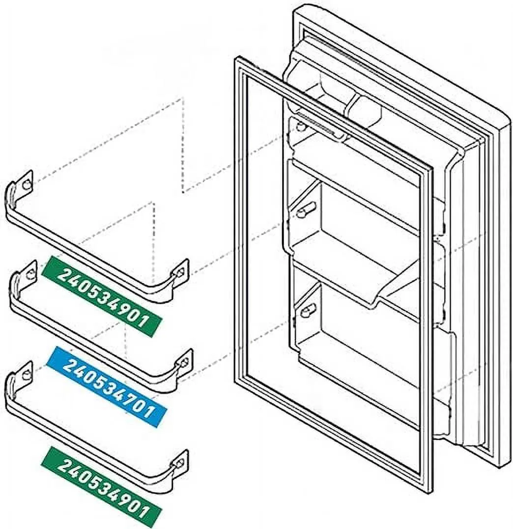
Examine the internal shelving system carefully. The door seal is vital for maintaining temperature consistency. Inspecting the hinges and latches on the door is important, as they directly affect how well the unit seals and performs. Any issues with alignment or wear can lead to inefficiency.
In the control compartment, focus on the thermostat and defrost timer. The thermostat controls the temperature and is often one of the first components to fail if the cooling system is malfunctioning. The defrost timer manages the defrost cycle and should be reset or replaced if necessary.
Don’t overlook the drainage system. Check for blockages in the drain pan or pipe, as accumulated water can cause further damage. Lastly, ensure the wiring is intact, as loose connections or frayed wires can disrupt electrical flow, leading to operational issues.
Identifying Common Appliance Components
The compressor is a critical part responsible for circulating refrigerant through the system. It’s located at the bottom of the unit, typically near the back. A malfunction can lead to temperature inconsistencies, and signs of failure include strange noises or the inability to cool effectively.
The evaporator fan is another vital element. It helps distribute cold air throughout the compartments. Often found near the cooling coils, it should be checked if there’s uneven temperature or air flow problems. If it’s making noise or not running, replacement may be needed.
The thermostat controls the temperature and is usually located inside the unit or attached to the control board. When temperatures are not stable, the thermostat could be the culprit. You can test it using a multimeter to ensure proper functionality.
Look for the condenser coils, typically at the back or beneath the appliance. They release heat from the refrigerant. If these coils become dirty, cooling efficiency can decrease. Clean them regularly with a coil brush or vacuum to maintain optimal performance.
The door seal or gasket is crucial for preventing cold air from escaping. Over time, it can degrade, leading to energy loss. Check it for cracks or gaps and replace it if necessary to avoid excessive power consumption.
The defrost heater is responsible for preventing ice buildup in the freezer. It works in tandem with the defrost timer and thermistor. If the freezer becomes frosty, inspect the heater and associated components to ensure they are functioning correctly.
How to Use a Refrigerator Component Schematic for Troubleshooting

To effectively resolve issues with your cooling appliance, follow these steps using the component schematic:
- Identify the Problem Area: Before consulting the schematic, pinpoint the area where the malfunction occurs. Common problems include inconsistent cooling, noise, or water leakage.
- Refer to the Key: Locate the key or legend typically included in the schematic. This section explains symbols and part numbers, making it easier to understand the drawing.
- Locate Relevant Components: Find the exact component based on your problem. For instance, if the issue involves temperature fluctuations, focus on parts like the thermostat or compressor.
- Check Connections: Inspect the connections of the selected component. Loose or damaged wires often cause malfunctions, so verify these are secure and intact.
- Verify Part Numbers: Match the part numbers on the schematic with the actual parts in your appliance. Ensure no replacements are needed for specific components.
- Test Components: Using the schematic, test individual components like the fan motor or evaporator coil. Each part should meet the specified voltage and resistance values.
- Consult Troubleshooting Guide: If the schematic does not provide enough information, consult the manufacturer’s troubleshooting guide for advanced diagnostic steps.
Using this methodical approach, you can easily isolate and fix issues in your appliance, saving both time and repair costs.
Step-by-Step Guide to Replacing Appliance Components

Before starting, disconnect the appliance from its power source to avoid electric shock. If replacing the compressor, ensure the cooling system is empty to prevent refrigerant leakage.
1. Identify the malfunctioning element using the provided reference chart. For a door seal, carefully inspect for tears or gaps. For the cooling fan, check if it’s obstructed or damaged.
2. Use the appropriate screwdriver to remove screws securing the defective component. Some parts may require a wrench or pliers for proper disconnection.
3. For insulation or gasket replacements, gently pry the old seal off. Clean the surface thoroughly before installing a new seal to ensure proper adhesion.
4. When removing electrical components, such as a thermostat or temperature sensor, label the wires to ensure correct reinstallation. Use a multimeter to test the continuity of the wires before connecting new components.
5. Install the new part by aligning it with the mounting holes or connecting points. For a fan motor, ensure it spins freely after installation. Tighten the screws securely, but do not overtighten to avoid damaging the housing.
6. If replacing a water filter or valve, connect the water line properly and check for leaks before reassembling the housing or paneling.
7. Once all components are in place, reconnect the appliance to power and test the functionality. Monitor for any unusual noises or leaks that may indicate improper installation.
8. Dispose of the old parts responsibly. Some components, like compressors or filters, may contain hazardous materials and require special disposal methods.