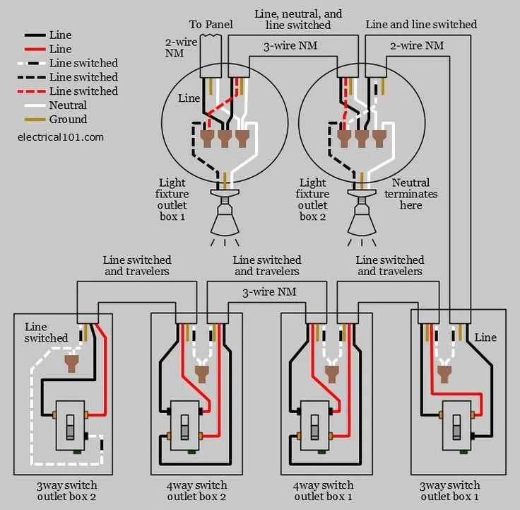
To set up a four-point control mechanism, you need to connect the circuits correctly to ensure smooth operation. Begin by connecting two control units to the electrical circuit that will serve as the initial points of operation. From there, the two intermediary units will bridge the connection and enable the user to control the lighting or device from any of the four locations. Make sure that each point is connected to the correct wire, ensuring the proper flow of energy.
At each control point, the terminals must be configured properly. The terminals at the two ends should be set as the input and output, while the two intermediary units should manage the flow between them. It’s essential to double-check each wire for continuity to avoid malfunctioning, especially when dealing with complex multi-point connections. Pay attention to the color coding of the wires and make sure to connect the live wire to the appropriate terminal for consistent results.
To complete the setup, test the entire circuit after everything is connected. Turn on the power and verify that you can switch the flow from any control unit. If there’s an issue, inspect each junction and ensure the wires are properly connected. This configuration is essential for providing convenience in large spaces where lighting or devices need to be operated from multiple locations, offering flexibility and control in one system.
How to Connect a 4-Way Electrical Setup

To establish a four-point control system, you need to ensure proper connections between the traveler terminals and the two control points. Start by connecting the common terminal of the first device to the power source. The travelers then connect to the corresponding terminals of the next control unit, ensuring that one terminal in the middle unit is connected to the power and the other to the load. Finally, the output terminal should lead to the light or the intended load. Proper grounding of all elements is essential for safety.
Use only quality connectors and double-check that all wires are securely fastened to prevent accidental disconnections. If you’re uncertain, always consult a licensed professional to handle the installation, as incorrect wiring can lead to malfunction or safety hazards.
Understanding the Basic 4-Way Switch Setup

To set up a four-way circuit, you need two intermediate devices placed between two three-way devices. The wiring configuration allows control of a light from multiple points in the same circuit. For efficient installation, ensure the following connections:
Step 1: Connect the two three-way devices to the main power source, where the incoming live wire enters the first switch.
Step 2: Use the traveler wires to connect the first three-way switch to the intermediate switches. These wires will carry current between the devices depending on their position.
Step 3: The outgoing neutral wire should be directly connected to the light fixture to complete the circuit.
Step 4: The load wire, which controls the light, must be routed from the last device to the fixture, ensuring it only receives power when one of the switches is on.
Remember that when wiring this configuration, the travelers do not carry the ground connection, so be sure to connect the ground to the devices and metal boxes as needed. Properly testing each switch position helps verify that the system works as expected before finalizing installation.
Troubleshooting Common Issues with 4-Way Circuit Connections
If the setup isn’t working correctly, start by ensuring that all connections are tight and secure. Loose or improperly connected wires often lead to malfunctioning circuits.
- Check the traveler connections between devices. A common issue arises when these connections are swapped or disconnected.
- Test the neutral connection. If it’s not properly linked, the circuit might not complete the path for electricity, causing the setup to fail.
- Ensure that the grounding is done correctly. Inadequate grounding can cause faulty operation or even create safety hazards.
- Inspect the load terminals. Miswiring here can prevent the device from functioning as expected.
For advanced troubleshooting, use a multimeter to check the voltage at different points along the circuit. This can help identify where the power is being interrupted or where a malfunction might be occurring.
- If there is no power at all, check the main power source. It may be disconnected or tripped.
- If only one component is non-functional, inspect the terminals at both ends of the connection for possible wear or breakage.
Lastly, replacing faulty components (like broken terminals or damaged wires) can restore normal function. If unsure, consult with a licensed electrician to ensure the circuit is wired safely and properly.