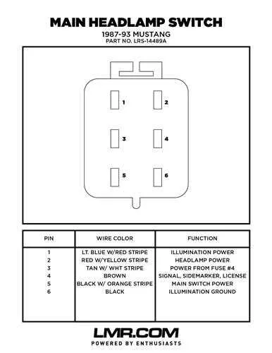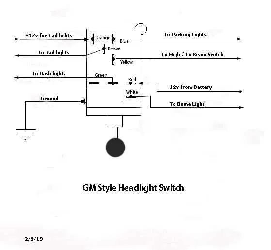
For efficient installation of the control mechanism that activates the front illumination system, follow the specific layout of electrical conductors connecting the power source, relay units, and the activation knob. Precise adherence to pin assignments ensures correct current flow and prevents circuit failures.
Key recommendation: Identify terminals responsible for low beam, high beam, and parking lights separately. Confirm the presence of a ground line and a power feed line to avoid short circuits or dim lighting issues.
Using a multimeter to verify continuity and voltage at each contact point improves troubleshooting accuracy during assembly or repairs. Always consult the vehicle’s manual for connector color codes and terminal numbering for your exact model.
Lighting Control Circuit Layout
Connect the main power source directly to the input terminal of the control unit to ensure stable voltage supply. Use a fuse rated at 15A between the battery and the control module to protect against short circuits. The output terminals must be linked to the illumination bulbs through high-quality connectors to avoid voltage drops.
Ground the chassis terminal securely to maintain a consistent return path. For vehicles with multiple light levels, include a multi-position selector relay with clear identification for each contact. Use color-coded cables: red for power feed, black for ground, and yellow for signal lines to simplify troubleshooting.
Incorporate a relay coil controlled by the dashboard toggler to manage current flow without overloading the manual controller. Confirm continuity and absence of shorts using a multimeter before final assembly. Shield wires routed near the engine compartment to prevent heat damage and interference.
For advanced setups, integrate an automatic dusk sensor input that overrides manual control when ambient light falls below a threshold. Label all terminals clearly on the schematic to facilitate future maintenance or upgrades.
Identifying Wire Colors and Functions in Headlight Switch Circuits

Start by locating the connector behind the control module. Use a multimeter to test each conductor with the ignition on and the lighting system off, then with each lighting function activated one by one.
Common color codes: Black typically indicates ground. Red or yellow often carries power from the fuse box. Brown or gray may lead to parking or running illumination. Blue or white frequently corresponds to high beam output. Green can serve multiple roles–verify with voltage readings under various conditions.
Function mapping: A wire showing 12V only when the stalk is in the low-beam position likely leads to the respective lamp circuit. If voltage appears only during high-beam activation, mark that as the long-range illumination output. A wire that remains energized regardless of dimmer position might connect to the tail lamp system or instrument cluster backlight.
Tip: When color codes are inconsistent, label each lead during testing. Use painter’s tape and a fine-tip marker to avoid mix-ups during reassembly or replacement.
Step-by-Step Process to Connect a Headlight Switch Wiring Harness
Begin by disconnecting the negative terminal of the battery to avoid shorts or sparks during installation. Locate the factory connector behind the dashboard panel, typically accessible after removing the trim near the steering column.
Identify each wire by color code: common configurations include red or orange for power input, brown or yellow for tail lamps, green for low beams, and blue or white for high beams. Cross-check these with the vehicle’s service manual before proceeding.
Use a multimeter to verify voltage on the power feed with the ignition on. Confirm ground presence on the appropriate terminal using the continuity setting.
Insert the harness plug into the control unit until it clicks. Avoid forcing the connector; if resistance is met, double-check alignment. Secure the bundle with zip ties to prevent movement that could lead to fraying or disconnection over time.
Reconnect the battery and test all positions: parking lamps, low beam, high beam, and instrument panel lighting. If any function fails, inspect individual wire pins for misalignment or corrosion.
Once functionality is verified, reassemble the dashboard trim and confirm that no wires are pinched or under tension. Always route the bundle away from sharp edges or heat sources like heater ducts or metal brackets.
Troubleshooting Common Wiring Issues in Headlight Switch Installations
Start by checking the ground connection near the lighting harness; poor grounding is a frequent cause of flickering or non-functional beams.
- Verify continuity between the dimmer lead and the chassis; resistance above 1 ohm may indicate corrosion or a broken conductor.
- Inspect the fuse panel for blown fuses; replace with the exact amperage to avoid overloading circuits.
- Use a test light to probe the output terminal while toggling between low and high beams; absence of voltage typically signals a faulty selector or open circuit.
- Disconnect the control plug and measure voltage directly from the power feed; anything below 12V under load can indicate a weak connection upstream.
- Trace the beam selector line for signs of melted insulation or sharp bends near pivot points, especially where the loom enters the cabin firewall.
If illumination works intermittently:
- Wiggle each connection point to detect unstable terminals.
- Examine splices for cold solder joints or improperly crimped connectors.
- Confirm the integrity of relay contacts, particularly if buzzing or heat is present.
When diagnosing complete failure:
- Bypass the control module using a jumper to rule out switchgear failure.
- Cross-reference wire color codes with factory charts to avoid misrouting leads.
- Test resistance between output and load ends to check for internal breaks within insulation.