Begin with a regulated 12 V supply and a three-core cable rated for at least 1 A per module to ensure uniform brightness across all bulbs. Select #22 AWG conductors for runs under 5 m; upgrade to #20 AWG when extending beyond to prevent voltage drop. Maintain consistent polarity by color‑coding each line: positive feed, return path, and control signal.
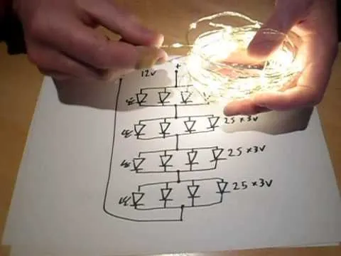
Position groups of ten diodes in parallel strings, each drawing roughly 20 mA, and connect their leads to the three-core harness. Integrate a common ground rail and separate data conductor for dynamic effects. Install 100 Ω resistors on each string junction to balance current and avoid premature burnout under varying temperatures.
Use insulated spade connectors at each segment junction to simplify maintenance and module swaps. Test each section at full load before sealing with heat‑shrink tubing. Document conductor lengths and connector types in a concise parts list to streamline future repairs and expansions.
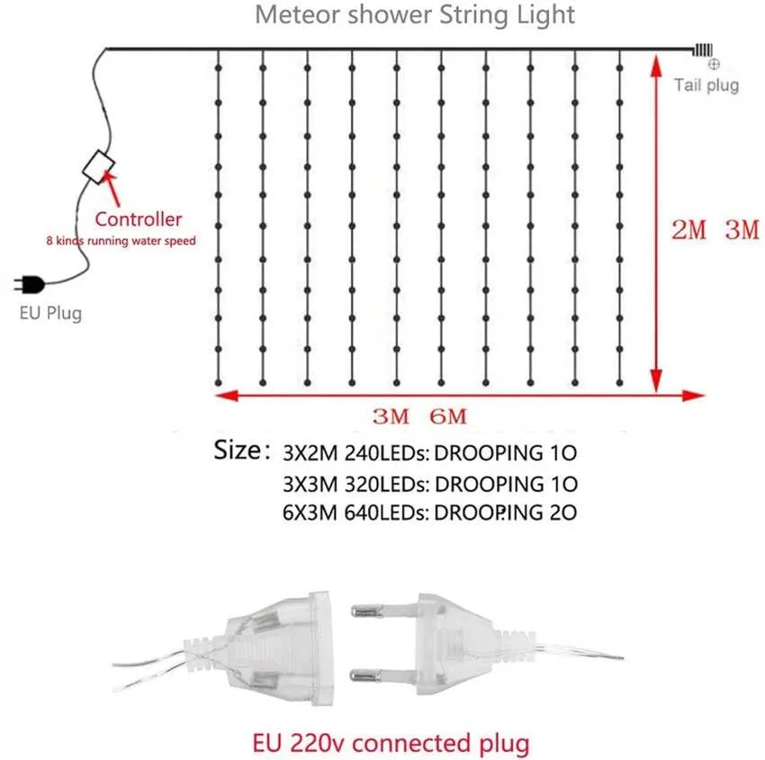
3-Conductor Festive Illumination Circuit Layout

Use 24 AWG stranded conductors rated for 300 V in a three-core assembly and suspend 60 diodes per strand. Group every five bulbs in series with a 220 Ω resistor to maintain a 20 mA current at 12 V, then parallel the resulting 12-bulb segments. Space each emitter at 10 cm intervals for uniform glow and seal solder joints with 80 °C shrink tubing.
Limit any single run to 15 m to keep voltage drop below 3%. Integrate a 330 Ω balancing resistor at each terminus for equal brightness across all segments. Choose PVC insulation with silicone overcoat to withstand –20 °C conditions. Before deployment, power-test each branch on a regulated 12 V bench supply, confirming 20 ± 1 mA per cluster.
Fasten the assembly onto a non‑conductive rail using nylon clips every 20 cm. Drive the trio core from a 12 VAC transformer with built-in current limiting. Route the central conductor as the common return and alternate the two outer feeds to create a two‑tone effect across every third diode. Expect a total draw of 1.2 A for a full 60‑unit chain.
How to Identify Line, Neutral, and Return Wires in a 3-Wire LED Holiday Circuit
Start by unplugging the string from any power source to avoid electrical hazards. Use a multimeter set to continuity or voltage detection mode to trace conductor roles accurately.
- Locate the plug end: The prongs on the plug help identify the hot (line) and neutral conductors. The narrower prong typically connects to the live path; the wider prong links to the neutral route.
- Test continuity from plug to output lines: Using a multimeter, check continuity from each plug prong to the three paths exiting the control module or first bulb base. This helps match each path to its role.
- Inspect insulation colors:
- Black or brown usually indicates the live path
- White or blue generally denotes neutral
- Red or green often corresponds to the return conductor for blinking or multi-phase operation
- Verify with voltage testing: Power the strand and carefully probe each path relative to ground. The hot path should show ~120V (in US systems), the neutral should show 0V relative to ground, and the return line may vary depending on control mode.
- Check internal layout of a single socket: Open one bulb holder and observe the internal contact structure. The return conductor often routes to the third contact separated from the standard power loop.
Document your findings before reassembly to ensure safe reconnection and future maintenance.
Wiring Configuration for Integrating a Blinker Controller into a 3-Conductor Festive Lighting Setup
Connect the hot line from the power source directly to the input terminal of the blinker controller. Ensure the neutral conductor bypasses the controller and links straight to the common return of the illumination strands.
The output of the blinker module should split into two paths, each leading to the individual active channels of the decorative array. These usually correspond to separate colors or alternating sections within the string. Verify that each return pathway is unified at the neutral junction to maintain continuity.
Use a multimeter to confirm continuity and correct voltage at each termination point before energizing the system. Incorporate an inline fuse rated slightly above the total current draw of the entire chain for overcurrent protection. Secure all splices with heat-shrink tubing or weatherproof caps to prevent moisture ingress.
Troubleshooting Common Failures in 3-Conductor Holiday Illumination Circuits

First, verify continuity across all three conductors using a multimeter set to resistance mode; breaks in any path will cause partial or total outage. Focus on the middle conductor, often serving as a shared return, since damage here frequently interrupts multiple segments.
Inspect all connectors and junction points for corrosion or loose contacts, as oxidation increases resistance and leads to flickering or dimming effects. Clean or reseat terminals to restore proper current flow.
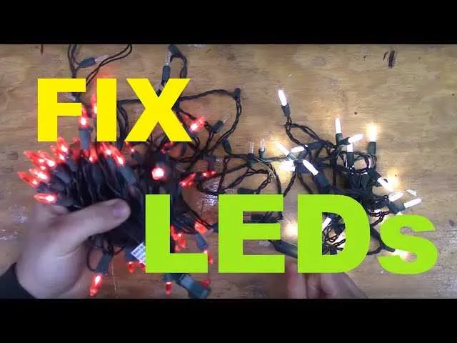
Check for burnt or damaged diodes within individual bulbs–faulty components disrupt the current flow and can create open circuits. Replace defective units promptly to prevent cascading failures.
Measure voltage at various nodes along the strand to detect voltage drops indicating overloaded or damaged sections. Excessive drop can point to insulation breaches or conductor thinning.
Use a specialized tester designed for multi-conductor festive strands to identify shorts between conductors or to ground, which often cause sections to remain dark or blink erratically.
When replacing bulbs, ensure compatibility with the specific current and voltage ratings of the system to avoid overloading and premature failure.
For consistent troubleshooting, document each tested segment and its status, facilitating identification of recurring issues or progressive damage over time.