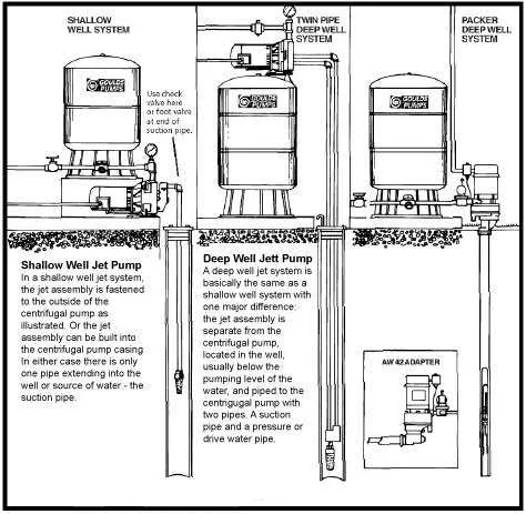
For efficient fluid lifting in deep reservoirs, consider using a submersible pump system with a nozzle-based mechanism that utilizes pressure from a primary fluid to push liquids upward. The setup typically involves an engine that drives the flow, generating a vacuum that enables the fluid to rise from an underground source.
The key components of such a system include the inlet, which draws in the fluid, and the ejector that expels the lifted liquid. The venturi tube creates the necessary pressure differential, enabling the movement of liquids with minimal energy loss. Proper installation ensures maximum efficiency, preventing cavitation and enhancing suction capabilities.
For smooth operation, ensure the intake valve is positioned correctly and that the suction line remains clear of debris. Additionally, the motor should be appropriately matched to the depth and volume requirements of the source, preventing overload and ensuring reliable performance.
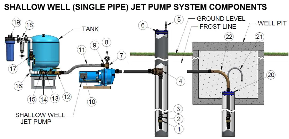
Diagram for Groundwater Extraction System

To properly install an underground fluid extraction system, ensure that the suction and discharge lines are appropriately sized. Use a diagram that shows the placement of the motor, ejector, and venturi to maximize efficiency. The intake pipe should be designed to avoid air locks, with a foot valve at the bottom to prevent backflow. Additionally, consider the depth of the source and the pressure required to lift the fluid to the surface without loss in volume.
Identify the optimal location for the intake and check valve to reduce any friction loss. The pressure switch should be installed near the tank to monitor system performance and maintain consistent flow. Be mindful of the electrical connections and grounding for safety and reliability. The system should also have a built-in check valve to maintain pressure and prevent the reverse flow of fluids when the system is inactive.
For a more effective design, focus on creating a sealed chamber around the ejector to ensure the maximum vacuum is maintained. Use a sturdy housing for all components to withstand varying conditions of pressure and temperature. The orientation of pipes plays a crucial role in preventing air from entering the system, so ensure there are no sharp turns that could cause blockages or inefficiency.
Verify that all components, such as seals and gaskets, are correctly installed to prevent leaks, which can significantly decrease the system’s overall performance. Finally, regularly inspect the system to confirm the pressure settings are accurate and adjust them if needed for optimal operation.
Understanding the Key Components of a Water Extraction System

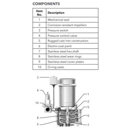
Focus on the following essential elements when working with an extraction system designed to draw liquids from underground sources:
Motor: The motor is the heart of the system. Choose one with the right power output to ensure efficient operation. It determines the flow rate and pressure of the extracted liquid. Opt for a motor that matches the requirements of the specific task at hand to avoid unnecessary energy consumption.
Injector: The injector is responsible for creating a suction effect. This part plays a crucial role in drawing liquid from the source. Make sure to regularly clean the injector to maintain proper functionality and prevent clogging.
Venturi: Located within the system, the venturi controls the fluid dynamics. Its function is to convert energy, enhancing the system’s performance. Regular inspection of this part is critical for ensuring optimal flow rates and pressure stability.
Discharge Head: The discharge head directs the flow towards the destination. Its design affects the pressure and volume of the delivered liquid. Make adjustments based on the required distance and pressure at the output point.
Check Valve: A check valve prevents reverse flow and ensures that the liquid remains in the system when not in use. This part should be carefully calibrated to match the pressure rating of the rest of the components.
Intake: The intake is the entry point for the liquid. Its size and positioning are critical for maximizing efficiency. Ensure the intake is well-filtered to avoid contaminants from entering the system.
Maintaining these components will extend the lifespan of the entire assembly. Proper installation, regular checks, and replacement of worn-out parts will prevent common issues like reduced efficiency or system failure.
How the Pump Functions to Lift Liquids
To effectively raise fluid from deep sources, the system relies on a combination of suction and pressure forces. The motor creates a vacuum, drawing liquid into the intake. A constricted nozzle directs this flow through a venturi, causing the liquid to gain speed while lowering its pressure. The surrounding atmospheric pressure then forces the liquid into the suction chamber, allowing it to be transported to the surface.
The motor’s role is essential in maintaining consistent flow rates. As it drives the impeller, centrifugal force pushes the liquid toward the discharge outlet. The high-speed fluid stream creates a low-pressure area, pulling more liquid from the source. This continuous action sustains the flow, overcoming gravitational forces that would otherwise prevent fluid from rising.
For proper operation, ensure the system is primed to avoid air pockets, which can disrupt the suction process. Regular maintenance of the motor and seals is crucial to prevent leaks and maintain consistent performance. Always verify the pressure and flow specifications to match the system’s design and avoid overloading.
Common Issues with Submersible and Surface Pumps and How to Troubleshoot Them
If your system isn’t functioning properly, follow these steps to identify the problem quickly:
- No Water Flow: Check for a clogged intake or blocked pipes. Remove any debris or sediment that may be obstructing the flow. Inspect the check valve for signs of malfunction.
- Low Pressure: This could be due to air trapped in the system. Bleed the air by releasing pressure through the system’s valve. If that doesn’t work, check the motor’s power supply and inspect the pressure switch.
- Motor Doesn’t Start: Ensure the power source is connected and functional. Test the electrical components, including the capacitor and switch. If the motor is overheated, let it cool down before retrying.
- Excessive Noise: Listen for unusual sounds such as grinding or rattling. This may indicate a malfunctioning impeller or bearing. Open the casing to inspect and lubricate as necessary.
- Frequent Cycling: Check the pressure switch settings and adjust if needed. Also, ensure the expansion tank is properly charged and functioning to prevent rapid cycling.
Regularly inspect the components for wear and replace faulty parts before they cause major damage. Proper maintenance and monitoring are key to long-lasting performance.