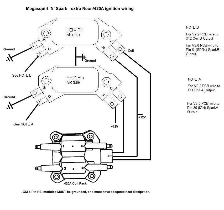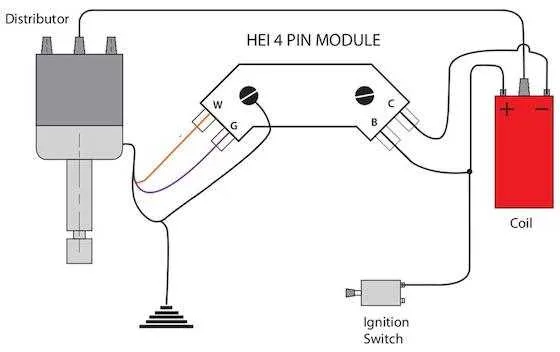
When setting up the ignition system in GM engines, it’s crucial to follow the right sequence for connecting the ignition components. Start by attaching the main power wire from the battery to the terminal of the ignition control unit, ensuring a secure and stable connection. This wire should be of sufficient gauge to handle the current required for the system to function effectively.
The coil’s primary wire, typically a thick lead, must be connected directly to the control unit. This is where the system gets its electrical energy to generate the spark needed to ignite the air-fuel mixture in the engine. Ensure that this connection is tight and free from any potential short circuits or loose contact points.
Next, connect the signal wire from the control unit to the coil’s secondary terminal. This wire is responsible for transmitting the pulses that activate the ignition coil and generate the high-voltage output. A proper grounding for the system is critical, as it ensures that the electrical flow remains stable and minimizes the risk of misfires.
Ensure correct placement of each wire to avoid any interference or electrical faults. Double-check that all connections are firmly secured and that the wires are routed away from heat sources or sharp edges, which could cause wear over time. A clear understanding of each connection’s function will prevent common issues such as weak sparks or engine stalling.
Wiring Setup of GM HEI Ignition System
To properly connect the GM HEI ignition system, start by ensuring a direct connection to the battery’s positive terminal. This will provide the necessary power to the module. Make sure to use a fused wire of at least 12-gauge for the power lead. For a reliable spark, the connection to the coil must be secured, with the wire going to the primary side of the ignition coil.
Ignition Switch Lead: The ignition switch lead should be connected to the “tach” terminal of the module. This ensures that the engine will only run when the switch is in the ON or START position, preventing unwanted activation of the system.
Grounding: A solid ground connection is crucial. Attach a wire to the distributor housing and route it to the vehicle’s chassis. This ensures the proper operation of the ignition components and prevents potential issues due to poor grounding.
Coil and Spark Lead: The secondary lead from the ignition coil goes to the rotor. This sends the high voltage needed to produce a spark in each cylinder. Ensure that all connections are clean and secure to avoid misfires.
When working with the wiring setup, avoid using old or worn-out connectors, as these may result in intermittent connections and ignition failures. Always verify the integrity of each lead and ensure proper insulation to prevent shorts and electrical hazards.
Understanding the Pinout and Wire Connections of GM HEI Distributor
To properly connect the ignition system components, start by identifying the key pins on the module. The primary wire should be connected to the positive terminal of the ignition coil, ensuring a steady voltage supply. The tachometer wire typically links to the negative terminal of the ignition coil for signal transmission. The 12V supply for the system comes from a direct line to the battery or the fuse block, providing consistent power. Ensure that this connection is fused to avoid overloads.
The ground connection, often overlooked, plays a vital role in stabilizing the ignition system. It must be securely attached to a solid engine ground point, minimizing voltage spikes or erratic spark patterns. The module itself typically has a dedicated ground pin to link directly to the chassis.
The connection to the control module is another critical part. The trigger wire from the distributor should connect to the control unit, with precise timing for accurate firing sequences. If you’re using a distributorless system, be mindful of the signal sync between the control unit and the ignition components.
Always check the manufacturer’s specifications for correct pinout configurations to avoid damage. If using aftermarket components, consult the wiring charts specific to your brand for adjustments or variations in pinout design.
Step-by-Step Guide to Installing GM HEI Distributor Wiring

Start by locating the ignition control module and ensuring the correct ignition coil is mounted. Identify the power source and ground connections, ensuring they are clean and securely connected. The positive lead should connect directly to the terminal marked “BATT” on the ignition module. Secure the ground wire to the vehicle’s chassis or battery ground point.
Next, connect the tachometer lead to the “TACH” terminal on the ignition system. This wire is essential for monitoring engine performance and should be routed away from other high-voltage wires to avoid interference.
Attach the ignition coil secondary wire to the output terminal of the ignition coil. Double-check that this wire is firmly in place to avoid misfires or weak spark production.
The last step involves the signal wire from the ignition switch. Connect it to the “P” terminal, ensuring there is a proper connection to send the necessary voltage when the engine is cranking.
After everything is connected, turn on the ignition and verify that all components are functioning correctly. A spark tester can confirm the strength of the signal being sent to the spark plugs.
Troubleshooting Common Electrical Issues in GM Ignition Systems
To address frequent problems with GM ignition setups, begin by verifying the connection to the power supply. Ensure that the power feed is securely attached to the primary coil terminal, as any loose connection can prevent proper ignition function.
- Check for corrosion or damage at the terminal contacts; clean or replace as needed.
- Test voltage using a multimeter to ensure adequate current flow to the coil.
Next, inspect the signal wire leading to the control module. Any signs of wear, fraying, or short circuits could cause intermittent or no spark. If this wire is compromised, replace it immediately to restore reliable spark signal transmission.
- Verify that the module’s ground connection is intact and free of rust or dirt.
- Make sure that no wires are pinched, as this could lead to shorting against the engine block.
Another common issue arises with the ignition switch, which controls the current flow to the entire system. If the switch is faulty or loose, it can cause starting problems. Test the switch by manually applying voltage and checking for any inconsistencies in spark generation.
- Ensure the switch engages fully and delivers consistent current to the system.
- Replace any worn or malfunctioning ignition switches.
Finally, assess the connection to the tachometer. A loose or defective tach wire can cause inaccurate readings, affecting the performance of the ignition system. Confirm that the tach signal is properly grounded and that no damage has occurred to the wire.
- Ensure the tachometer ground is properly connected to prevent erratic engine behavior.
- If the tachometer reading fluctuates or the engine misfires, inspect and replace any faulty components in the tach wiring.