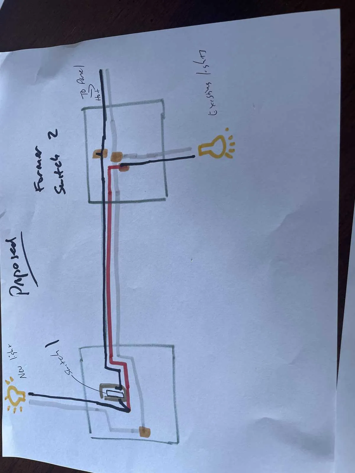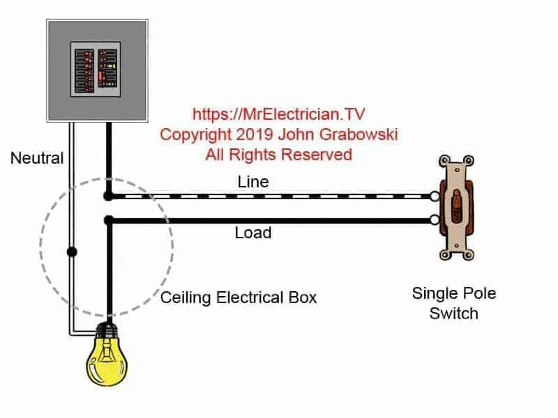
To connect a basic light control circuit, you need to ensure proper wire configuration between the power source and the light fixture. Start by identifying the live and neutral wires, ensuring correct polarity before making any connections. The key component in this setup is a device that controls the flow of current, which allows you to turn the light on or off from a single location. For the proper functioning of this system, follow the schematic carefully, connecting the live wire from the power source to the device’s input terminal.
Next, connect the output terminal of the control device to the light fixture. This ensures that the flow of electricity to the light can be interrupted or completed when the device is activated. Grounding is equally important; always connect the ground wire to avoid electrical hazards. If you are unsure of the wiring process, consult the manual of your specific device or seek professional advice to avoid accidents.
For safety, always ensure that the power is off before starting the installation. Double-check each connection to ensure no loose or exposed wires. Test the setup by turning the control device on and off to confirm that the light responds as expected. Following these steps will result in a reliable and safe light control setup suitable for most household applications.
Wiring a Basic On/Off Control
For a simple on/off control of a light or device, use a two-wire connection from the power source to the load. One wire runs from the power supply to the device, while the other connects the terminal of the controller to the load. This allows for breaking or completing the circuit with a single operation.
The key is to place the controller in series with the load, where it will control the flow of electricity to the device. Ensure that the connection to the live wire is made at the input side, and the output leads directly to the device you want to control. The neutral line should remain uninterrupted, passing directly to the device.
To ensure proper functioning, verify that the device is rated for the voltage and current you are controlling. Incorrect voltage ratings or overload conditions could lead to failure of the control unit or damage to the connected equipment.
When working with this setup, safety is crucial. Always turn off the power at the circuit breaker before making any adjustments. Double-check the wiring connections before testing the setup to avoid potential hazards.
How to Read a Circuit for a Basic On/Off Control
Start by identifying the key components: power source, load, and control device. These are usually shown by their respective symbols. The power source is typically marked with a pair of parallel lines, while the load, like a light, is represented by a circle with an “X” inside. The controller is depicted by a symbol with a line breaking the path, indicating where the connection can be opened or closed.
Follow the path from the power source to the load. The connection should flow through the control device, which acts as an interrupter. When the control is “closed”, electricity flows through, completing the circuit. When “open”, the flow is interrupted.
Important details to focus on:
- The terminal connections of the control device, usually marked with numbers like “1” and “2” or “COM” and “L”. These indicate where the wires should connect.
- The line wire (live) and neutral wire should be clearly differentiated. Often, the live wire is drawn in a solid line and the neutral in a dashed line.
- The control component typically has one line connecting to the live wire, and another to the load. Make sure there are no additional branches or loops that could suggest a more complex system.
Ensure the proper orientation of the components, as improper alignment can lead to malfunction. Also, confirm that the power supply is connected directly to the terminal of the load device for a consistent flow when activated.
In summary, reading this kind of circuit requires recognizing key components, following the flow path from power to load, and understanding the role of the controller in interrupting or completing the circuit.
Wiring a Basic On/Off Control: Step-by-Step Guide

Step 1: Turn Off Power – Before beginning any work, always turn off the circuit breaker to prevent electrical hazards.
Step 2: Gather Tools and Materials – You will need a screwdriver, wire stripper, electrical tape, a new control device, and wire connectors.
Step 3: Remove the Old Device (if applicable) – Use a screwdriver to remove the cover plate. Unscrew the existing unit and pull it out of the box. Ensure that all wires are disconnected safely.
Step 4: Prepare the Wires – Use a wire stripper to remove about 3/4 inch of insulation from the ends of the black (hot) wire, and the ground wire. If you’re working with a neutral wire, ensure it’s properly placed in the box, but do not connect it to the device unless required by local codes.
Step 5: Connect the Wires to the New Unit – Attach the black (hot) wire to the brass terminal on the device. If the ground wire is present, connect it to the green grounding screw. Tighten the screws to secure the wires in place.
Step 6: Install the New Device into the Box – Carefully tuck the wires into the electrical box, ensuring that they are not pinched. Screw the new unit into the box, making sure it is securely mounted.
Step 7: Attach the Cover Plate – Once the unit is in place, attach the cover plate to the device. This will help prevent exposure to electrical components.
Step 8: Turn On Power and Test – After securing everything, turn the power back on at the circuit breaker. Test the control by toggling it to ensure proper operation.
Common Troubleshooting Tips for Wiring a Basic Circuit Control
Check the power source: Ensure that the circuit is powered off completely before starting any work. Use a voltage tester to confirm that no current is flowing through the wires.
Verify wire connections: Inspect all wire connections, especially the terminals on the control device. Ensure that the live wire is connected securely to the input terminal and the load wire is connected to the output terminal. Loose connections can lead to intermittent operation or complete failure.
Test for continuity: Use a multimeter to check the continuity of the wiring from the control unit to the device being controlled. A lack of continuity may indicate a broken wire or loose connection.
Inspect for damage: Look for any visible signs of damage to the wires, insulation, or terminals. Burnt or frayed wires should be replaced immediately to prevent safety hazards.
Examine the control unit’s function: If there is no response when the device is operated, consider testing or replacing the control unit. A faulty mechanism can prevent proper operation, even if all wiring appears correct.
Check the ground connection: Ensure that the ground wire is properly connected. A missing or faulty ground connection can cause electrical malfunctions or pose safety risks.
Test the load device: Verify that the device being powered works correctly by testing it in a different circuit. A malfunctioning appliance can sometimes be the root cause of issues in the wiring system.
Inspect circuit breaker: If the system is not functioning, check the breaker panel to ensure that the circuit has not been tripped. Resetting the breaker may resolve the issue if it was triggered by an overload or fault.
Confirm correct wire gauge: Ensure that the wire gauge is appropriate for the load. Undersized wires can overheat, leading to potential failure or safety hazards.